Transformer coil winding and winding device comprising transformer coil winding

A technology of transformer coils and coils, applied in the direction of transformer/inductor coil/winding/connection, transformer/inductor components, inductor/transformer/magnet manufacturing, etc. Failure and other problems, to achieve the effect of saving insulating materials, avoiding high-voltage short circuits, and preventing collapse and loosening

Active Publication Date: 2020-10-02
SHENZHEN JINGQUANHUA ELECTRONICS
View PDF5 Cites 1 Cited by
  • Summary
  • Abstract
  • Description
  • Claims
  • Application Information

AI Technical Summary

Problems solved by technology

The short-circuit failure rate of the coil and the magnetic core will also increase sharply with the increase of the working time of the transformer
In addition, under high-voltage conditions, the place where the potential difference of the entire transformer is the largest, that is, between the coil starting wire and the tail wire, is prone to high-voltage breakdown of the transformer, which in turn leads to transformer failure and burning.
However, in the current coil design and practical application, there is no effective means to prevent the above problems

Method used


Image

  • Transformer coil winding and winding device comprising transformer coil winding
  • Transformer coil winding and winding device comprising transformer coil winding
  • Transformer coil winding and winding device comprising transformer coil winding

Examples


Embodiment Construction

[0046] The following will clearly and completely describe the technical solutions in the embodiments of the present invention with reference to the accompanying drawings in the embodiments of the present invention. Obviously, the described embodiments are only some, not all, embodiments of the present invention. Based on the embodiments of the present invention, all other embodiments obtained by persons of ordinary skill in the art without making creative efforts belong to the protection scope of the present invention.

[0047] In the invention, unless otherwise clearly specified and limited, the term "connection" should be interpreted in a broad sense, for example, the term "connection" can be a fixed connection, a detachable connection, or an integral connection; it can also be Mechanical connection; it can be directly connected, or connected through an intermediary, and can be internally connected between two components. Those of ordinary skill in the art can understand the...


PUM


Abstract

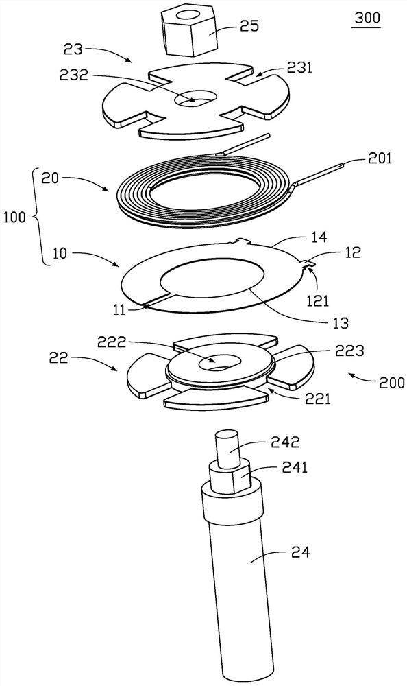
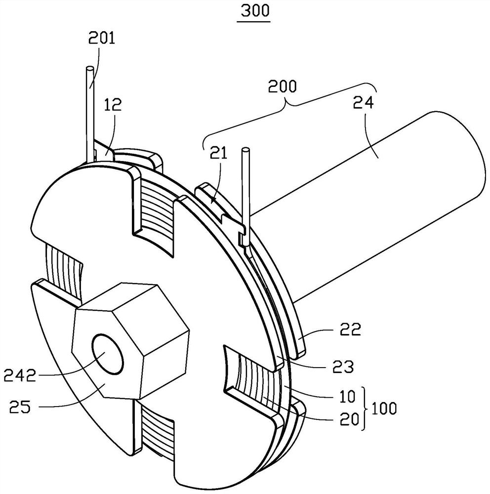
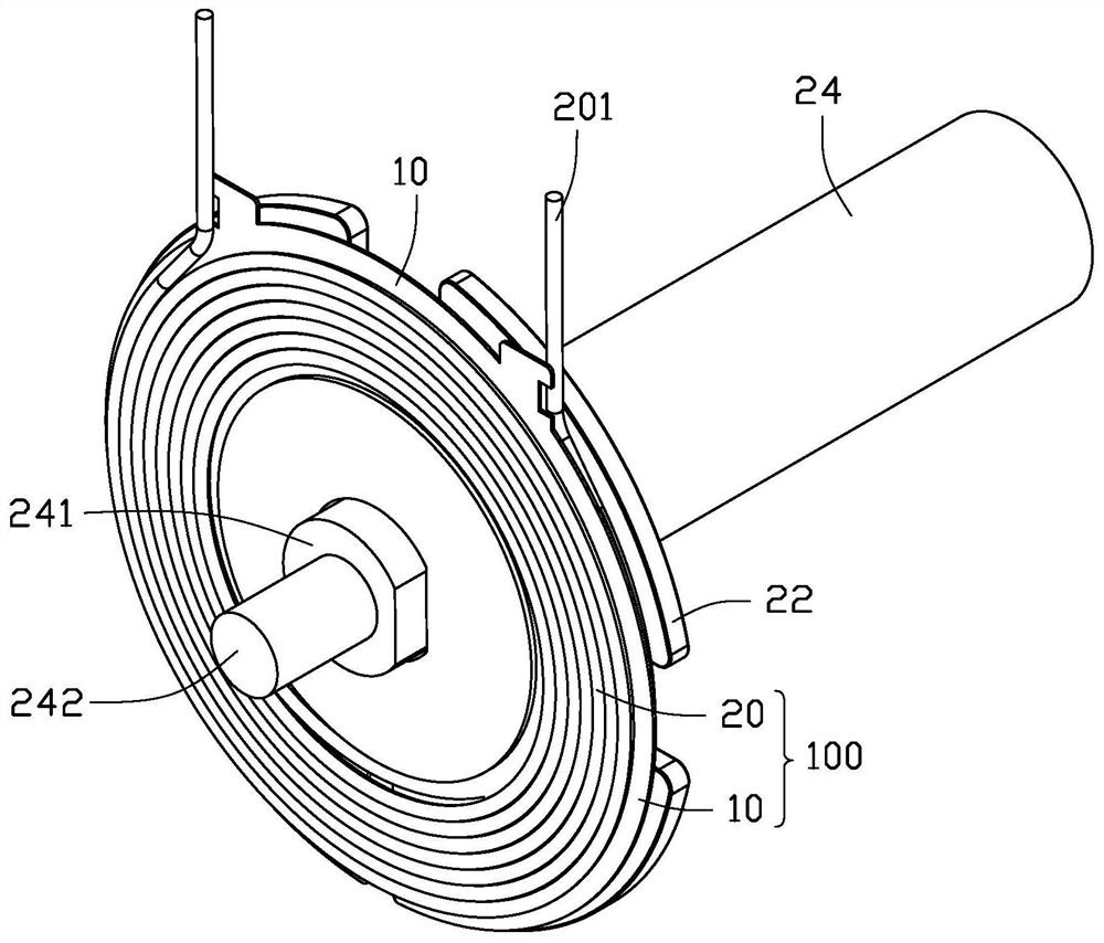
The invention discloses a transformer coil winding. The transformer coil winding comprises coils and an isolation piece, wherein the coils comprise a first coil and a second coil, and the first coil and the second coil are respectively formed by winding wires wound on the two sides of the isolation piece; the isolation piece is provided with an open groove, the wire is arranged in the open groovein a penetrating mode in the direction perpendicular to the isolation piece, and the open groove is used for dividing the wire into a first part and a second part; a first portion of the wire is woundon a first side of the isolation piece to form the first coil, and a second portion of the wire is wound on a second side of the isolation piece to form the second coil. According to the transformercoil winding, the coil can be prevented from collapsing and loosening, the boundary dimension of the coil is kept consistent, production and installation of the coil are facilitated, insulating materials are saved, and high-voltage short circuit between the coil and a magnetic core is avoided. The invention further provides a winding device comprising the transformer coil winding.

Description

technical field [0001] The invention relates to a transformer coil winding and a winding device comprising the transformer coil winding. Background technique [0002] In a transformer, the wire is usually wound in a double-layer pie shape with self-adhesive insulated wire to form a coil. However, after a single coil is installed in the window space of the magnetic core, the inner or outer wall of the coil will inevitably touch the center column or side column of the magnetic core, and during the working vibration of the transformer, the inner wall or the outer wall of the coil will inevitably touch the center column or side column of the magnetic core Or the side column for high-frequency friction. The short-circuit failure rate of the coil and the magnetic core will also increase sharply with the increase of the working time of the transformer. In addition, under high-voltage conditions, the place where the potential difference of the entire transformer is the largest, th...

Claims


Application Information

Patent Timeline
Patent Type & Authority Applications(China)
IPC IPC(8): H01F27/28H01F27/30H01F41/06H01F41/082
CPCH01F27/28H01F27/306H01F41/06H01F41/082
Inventor 鞠万金黄文华朱勇李伟刘榕青
Owner SHENZHEN JINGQUANHUA ELECTRONICS
Why Eureka
Try Eureka