Supercharge Your Innovation With Domain-Expert AI Agents!

Dielectric filter and communication base station

A technology of dielectric filters and dielectric resonators, which is applied in waveguide devices, electrical components, circuits, etc., can solve the problems of adding parts and processes, weak electric field coupling, and narrow application scenarios, so as to increase the amount of capacitive coupling , flexible coupling bandwidth, and the effect of reducing production difficulty

Pending Publication Date: 2020-10-02
ANHUI TATFOOK TECH CO LTD
View PDF1 Cites 4 Cited by
  • Summary
  • Abstract
  • Description
  • Claims
  • Application Information

AI Technical Summary

Problems solved by technology

[0003] Dielectric filters usually need to introduce capacitive cross-coupling to achieve strong suppression of transmission zeros. To achieve low-end transmission zeros and symmetrical transmission zeros, it is necessary to introduce a capacitive coupling structure (a single high-end transmission zero sometimes does not need to introduce a capacitive coupling structure. ), the traditional dielectric waveguide filter usually adopts the following forms to realize capacitive coupling: 1. The frequency-dependent coupling structure is adopted. Although the structure is simple, it will introduce an additional resonance point
2. The capacitive coupling structure derived directly from the fly rod structure of the traditional cavity filter is relatively complicated, and increases the parts and processes of the product
However, the two resonators of this solution are located on the same surface, the magnetic field coupling is strong, the electric field coupling is weak, and the application scenarios are narrow

Method used


Image

  • Dielectric filter and communication base station
  • Dielectric filter and communication base station
  • Dielectric filter and communication base station

Examples


Embodiment Construction

[0031] Now in conjunction with the accompanying drawings, the preferred embodiments of the present invention will be described in detail.

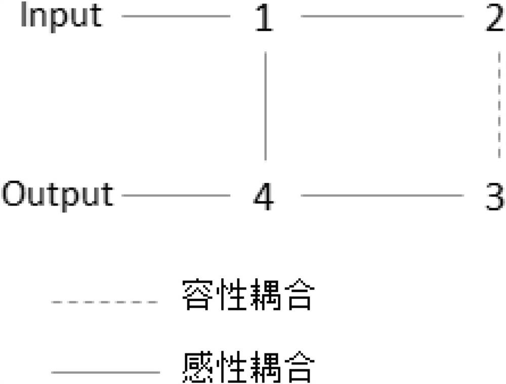
[0032] A dielectric filter such as Figure 1 to Figure 4 As shown, it includes a body 10 made of a dielectric material and at least a pair of dielectric resonators disposed on the surface of the body 10, between a first dielectric resonator 11 and a second dielectric resonator 12 of a pair of dielectric resonators A coupling window 16 and two coupling slots are provided. The first dielectric resonator 11 and the second dielectric resonator 12 are respectively located on the upper surface and the lower surface of the body 10, the first coupling grooves 13 are respectively located on the upper surface of the body, the second coupling groove 14 is located on the lower surface of the body, and the second coupling groove 14 is located on the lower surface of the body. A coupling slot 13 communicates with the second coupling slot 14 at least pa...


PUM


Abstract

The invention relates to a dielectric filter and a communication base station. The filter comprises a body made of a dielectric material and at least one pair of dielectric resonators arranged on thesurface of the body, two coupling grooves are formed between the first dielectric resonator and the second dielectric resonator of the pair of dielectric resonators, and the first dielectric resonatorand the second dielectric resonator are respectively located on the upper surface and the lower surface of the body. The two coupling grooves are respectively located on the upper surface and the lower surface of the body, the two coupling grooves are at least partially communicated, and capacitive coupling between the first dielectric resonator and the second dielectric resonator is realized through the coupling grooves. The invention has the technical effects that the coupling bandwidth can be simply and flexibly realized, no harmonic wave is generated, and the large-batch production is convenient.

Description

technical field [0001] The invention relates to a communication device, in particular to a dielectric filter cross-coupling technology. Background technique [0002] With the construction of 5G communication systems, the requirements for the integration of its equipment are getting higher and higher. The miniaturization and light weight of microwave filters are the future application trends. The dielectric waveguide has the advantages of high Q value and small temperature drift. It is a kind of Good filter miniaturization solution. [0003] Dielectric filters usually need to introduce capacitive cross-coupling to achieve strong suppression of transmission zeros. To achieve low-end transmission zeros and symmetrical transmission zeros, it is necessary to introduce a capacitive coupling structure (a single high-end transmission zero sometimes does not need to introduce a capacitive coupling structure. ), the traditional dielectric waveguide filter usually adopts the following...

Claims


Application Information

Patent Timeline
Patent Type & Authority Applications(China)
IPC IPC(8): H01P1/212H01P1/20H01P1/208
CPCH01P1/212H01P1/2002H01P1/208
Inventor 吴亚晖钟志波
Owner ANHUI TATFOOK TECH CO LTD
Features
  • R&D
  • Intellectual Property
  • Life Sciences
  • Materials
  • Tech Scout
  • Unparalleled Data Quality
  • Higher Quality Content
  • 60% Fewer Hallucinations
Learn More