Coaxial cavity filter

A filter and coaxial cavity technology, applied in waveguide devices, electrical components, circuits, etc., can solve the problems of fly rod sensitivity, filter ignition, etc., and achieve the effect of strong capacitive coupling

Inactive Publication Date: 2018-06-29
MOBILE ANTENNA TECH SHENZHEN +2
View PDF3 Cites 0 Cited by
  • Summary
  • Abstract
  • Description
  • Claims
  • Application Information

AI Technical Summary

Problems solved by technology

[0005] The purpose of the present invention is to solve the problem that in the coaxial cavity filter in the prior art, when the capacitive coupling is increased by increasing the flying rod, the problem that the flying rod is too sensitive or the filter is easily sparked

Method used


Image

  • Coaxial cavity filter
  • Coaxial cavity filter
  • Coaxial cavity filter

Examples


Embodiment Construction

[0019] Typical embodiments that embody the features and advantages of the present invention will be described in detail in the following description. It should be understood that the present invention is capable of various changes in different embodiments without departing from the scope of the present invention, and that the description and illustrations therein are illustrative in nature and not limiting. this invention.

[0020] In order to further illustrate the principle and structure of the present invention, preferred embodiments of the present invention will now be described in detail with reference to the accompanying drawings.

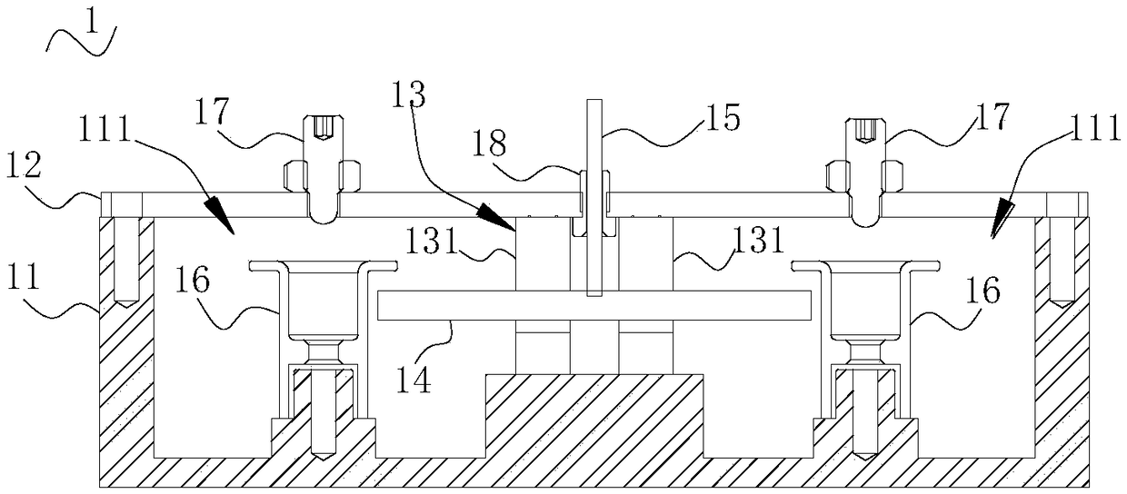
[0021] refer to figure 1 , the present application provides a coaxial cavity filter 1, which includes a main body 11, a cover plate 12, a supporting medium 13 and a coupling assembly.

[0022] Specifically, the top of the main body 11 is provided with an opening, and at least two resonant cavities 111 are provided inside the main body 11 . ...


PUM


Abstract

The invention provides a coaxial cavity filter which comprises a body, a cover plate, a support medium and a coupling assembly. An opening is formed in the top of the body. At least two resonant cavities are arranged inside the body; the cover plate covers the opening of the body; the support medium is arranged between every two adjacent resonant cavities; the coupling assembly comprises a fly rodand a connecting rod; the fly rod is penetratingly arranged in the support medium, and two ends of the fly rod extend into the resonant cavities on two sides of the support medium; one end of the connecting rod is connected onto the fly rod, and the other end of the connecting rod is connected with the cover plate. The coaxial cavity filter has the advantages that the fly rod does not need to belengthened to improve the capacitive coupling of the coaxial cavity filter when the cavity circle center distances of every two adjacent resonant cavities are farther than 1/4 of wavelengths due to reduction of internal spaces of the body, only the diameter of the connecting rod needs to be adjusted, accordingly, the capacitive coupling can be significantly regulated and controlled, the coaxial cavity filter is strong in capacitive coupling, and the problem of excessive sensitivity of existing fly rods or sparking of filters due to the fact that the ends of the existing fly rods approach resonant rods can be effectively solved.

Description

technical field [0001] The invention relates to the field of microwave communication, in particular to a coaxial cavity filter. Background technique [0002] With the rapid development of wireless mobile communication technology, coaxial filters are widely used in the communication field due to their advantages of being passive components, strong anti-interference, and being able to cope with various harsh environments. [0003] In the actual application process, due to the narrower and narrower spectrum isolation sections of different system networks and higher anti-interference requirements for the network, users have higher and higher requirements for the performance of cavity filters, especially the higher the requirements for mutual suppression. come higher. In order to meet the increasing rejection requirements, the out-of-band requirement of high rejection needs to be achieved through the cross-coupling technique of adjacent cavities, where the capacitive coupling ca...

Claims


Application Information

Patent Timeline
Patent Type & Authority Applications(China)
IPC IPC(8): H01P1/205
CPCH01P1/205
Inventor 郑奋立
Owner MOBILE ANTENNA TECH SHENZHEN
Why Eureka
Try Eureka