Passive corona field lightning dispeller for high-speed rail

A technology of passive lightning drive and corona field, which is applied in the field of high-speed rail lightning drive, to achieve the effect of simple fixed installation, avoiding lightning strikes, and ensuring the safety of high-speed rail operation

Active Publication Date: 2020-10-02
山东中呈防雷科技有限公司
View PDF8 Cites 1 Cited by
  • Summary
  • Abstract
  • Description
  • Claims
  • Application Information

AI Technical Summary

Problems solved by technology

[0003] The object of the present invention is to provide a kind of passive corona field mine drive device for high-speed rail, to solve the existing problems

Method used


Image

  • Passive corona field lightning dispeller for high-speed rail
  • Passive corona field lightning dispeller for high-speed rail
  • Passive corona field lightning dispeller for high-speed rail

Examples


Embodiment 1

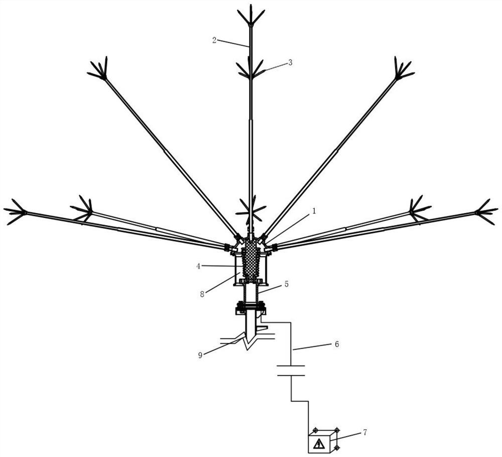
[0028] see figure 1 As shown, the present invention provides the following technical solutions: a passive corona field lightning drive for high-speed rail, including some passive lightning drives arranged at intervals along the high-speed rail track, and the passive lightning drive includes a bottom end with an opening A metal cover 1, a number of discharge rods 2 are evenly arranged on the outer wall of the metal cover 1, an insulating support 4 is installed on the inner wall of the opening end of the metal cover 1, and an electrode 5 is arranged at the bottom of the insulating support 4, between the electrode 5 and the inner wall of the metal cover 1 There is a discharge gap between them, and the ground wire 6 is connected to the electrode 5, and is connected to the earth through the ground wire 6.

[0029] In this embodiment, preferably, the distance between two adjacent passive corona field lightning drivers is 1-2 km.

[0030] In this embodiment, preferably, a discharge ...

Embodiment 2

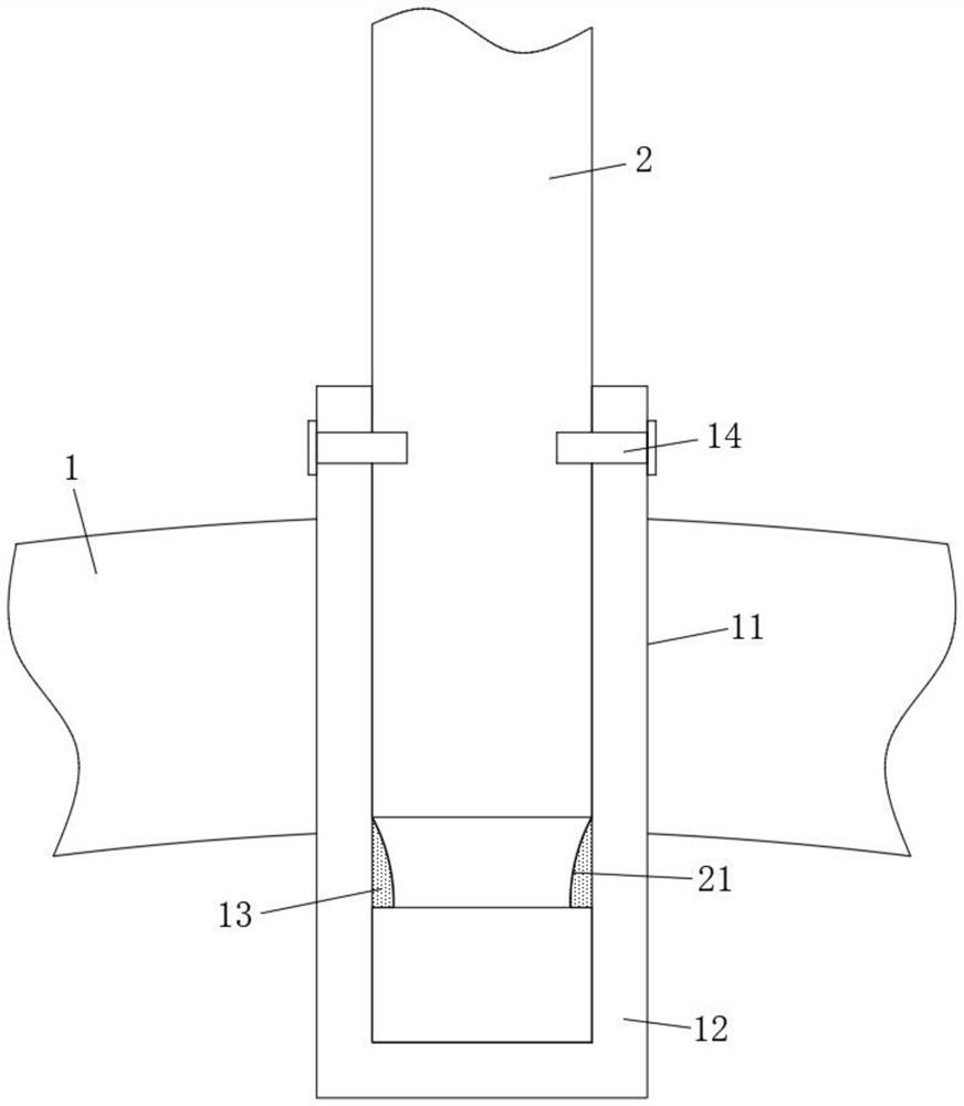
[0041] see figure 2 As shown, a plurality of discharge through-holes 11 are evenly opened on the metal housing 1, and a connection sleeve 12 is fixed through each discharge through-hole 11, and a plurality of discharge rods 2 are evenly fixed on the metal housing 1 through the connection sleeve 12,

[0042] In this embodiment, preferably, the inner wall of the connecting sleeve 12 is provided with a ring-shaped first buckle 13, and the outer wall of the discharge rod 2 is provided with a ring-shaped first locking groove 21, and the first locking groove 21 is connected with the first locking groove. The buckles 13 are engaged with each other.

[0043] In this embodiment, preferably, a first bolt 14 is fixed between the connection sleeve 12 and the discharge rod 2 , the first bolt 14 is located outside the metal housing 1 , and the first bolt 14 is coated with conductive thread glue.

[0044] Based on the structure disclosed in this embodiment, it can be seen that the principl...

Embodiment 3

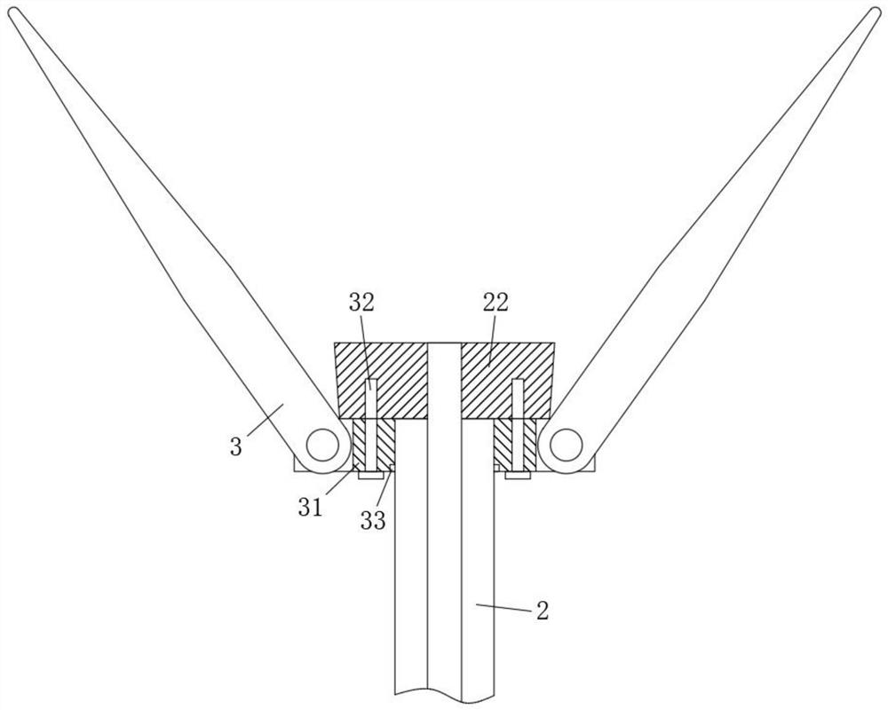
[0047] see Figure 3-Figure 4 As shown, the limit end 22 is welded on the end of the discharge rod 2 far away from the connecting sleeve 12, and the discharge rod 2 is also covered with a movable installation ring 31, and the discharge needle 3 is rotatably mounted on the installation ring 31, and the discharge needle The rotating installation structure of 3 includes a rotating shaft and a return spring connected between the rotating shaft and the mounting ring 31. A second bolt 32 is fixed between the limiting end 22 and the mounting ring 31, and the limiting end 22 is fixed to the mounting ring 31. , limit the discharge needle 3 to tilt outward.

[0048] In this embodiment, preferably, the second buckle 23 is set on the discharge rod 2, and the second buckle 33 is opened on the mounting ring 31, and when the second buckle 33 is engaged with the second buckle 23, the discharge Needle 3 is parallel to discharge rod 2.

[0049] Based on the structure disclosed in this embodim...


PUM


Abstract

The invention belongs to the technical field of high-speed rail building lightning expelling, and discloses a passive corona field lightning dispeller for a high-speed rail. The passive corona field lightning dispeller comprises a plurality of passive lightning dispellers which are arranged at intervals along a high-speed rail, wherein the passive lightning dispeller comprises a metal outer coverof which the bottom end is provided with an opening, a plurality of discharge through holes are uniformly formed in the metal outer cover, a connecting sleeve is fixed in each discharge through hole in a penetrating manner, a plurality of discharge rods are uniformly fixed on the metal outer cover through the connecting sleeve, an insulating support is arranged on the inner wall of the opening endof the metal outer cover, an electrode is arranged at the bottom of the insulating support, a discharge gap is formed between the electrode and the inner wall of the metal outer cover, and the electrode is connected with a grounding wire and is connected with the ground through the grounding wire. According to the invention, one side of the high-speed rail is provided with a plurality of passivelightning dispellers at intervals so as to effectively eliminate thunderclouds near the high-speed rail and guarantee the operation safety of the high-speed rail; and the passive lightning dispeller has the advantages of being convenient to transport and install.

Description

technical field [0001] The invention belongs to the technical field of lightning driving for building high-speed railways, and in particular relates to a passive corona field lightning driving device for high-speed railways. Background technique [0002] High-speed railway, referred to as high-speed railway, at present, my country's high-speed railway geographical areas are separated by a large span, and there is no backup system. In this case, once a lightning strike occurs, it will cause a permanent failure, and the power supply section will be out of service. The cost and technical requirements are high, the construction standards are strict and demanding, and the management and maintenance are complicated and difficult. Therefore, lightning protection work for high-speed railways is particularly important. In order to reduce the impact of lightning weather on high-speed rail, lightning rods are usually installed on high-speed rail or lightning conductors are installed on ...

Claims


Application Information

Patent Timeline
Patent Type & Authority Applications(China)
IPC IPC(8): H01T19/04H01T4/02H01T23/00H02G13/00H01R4/66
CPCH01T19/04H01T4/02H01T23/00H02G13/80H01R4/66
Inventor 袁存景邵立忠胡玉栋姚春林刘太杰宋翠梅袁野
Owner 山东中呈防雷科技有限公司
Why Eureka
Try Eureka