
Solar panel mounting bracket capable of self-adaptively adjusting angle

An adaptive adjustment, solar panel technology, applied in the direction of solar thermal energy, solar thermal power generation, solar collectors, etc., can solve the problems of high manufacturing and maintenance costs of brackets, difficult to achieve photovoltaic panels, unfavorable promotion and use, etc. The effect of promoting the use of area, reducing maintenance and maintenance costs, and simple structure

Inactive Publication Date: 2020-10-02
张东虎
View PDF2 Cites 4 Cited by
  • Summary
  • Abstract
  • Description
  • Claims
  • Application Information

AI Technical Summary

Problems solved by technology

[0003] In order to improve the power generation efficiency of solar energy, installation brackets that can automatically adjust the orientation angle of photovoltaic panels have appeared in the prior art; however, these installation brackets generally achieve angle adjustment through electronic components such as electric drive equipment and sensors, resulting in high manufacturing and maintenance costs for the brackets , which is not conducive to the promotion and use of large areas; at the same time, although the structure of some self-adjusting brackets is relatively simple, it is difficult to make the photovoltaic panels perpendicular to the sun's rays, and the power generation efficiency of photovoltaic panels is not maximized.

Method used


Image

  • Solar panel mounting bracket capable of self-adaptively adjusting angle
  • Solar panel mounting bracket capable of self-adaptively adjusting angle

Examples


Embodiment Construction

[0016] The following will clearly and completely describe the technical solutions in the embodiments of the present invention with reference to the accompanying drawings in the embodiments of the present invention. Obviously, the described embodiments are only some, not all, embodiments of the present invention.

[0017] In describing the present invention, it should be understood that the terms "center", "longitudinal", "transverse", "length", "width", "thickness", "upper", "lower", "front", " Orientation or position indicated by "back", "left", "right", "vertical", "horizontal", "top", "bottom", "inner", "outer", "clockwise", "counterclockwise", etc. The relationship is based on the orientation or positional relationship shown in the drawings, and is only for the convenience of describing the present invention and simplifying the description, rather than indicating or implying that the referred device or element must have a specific orientation, be constructed and operated in...


PUM


Abstract

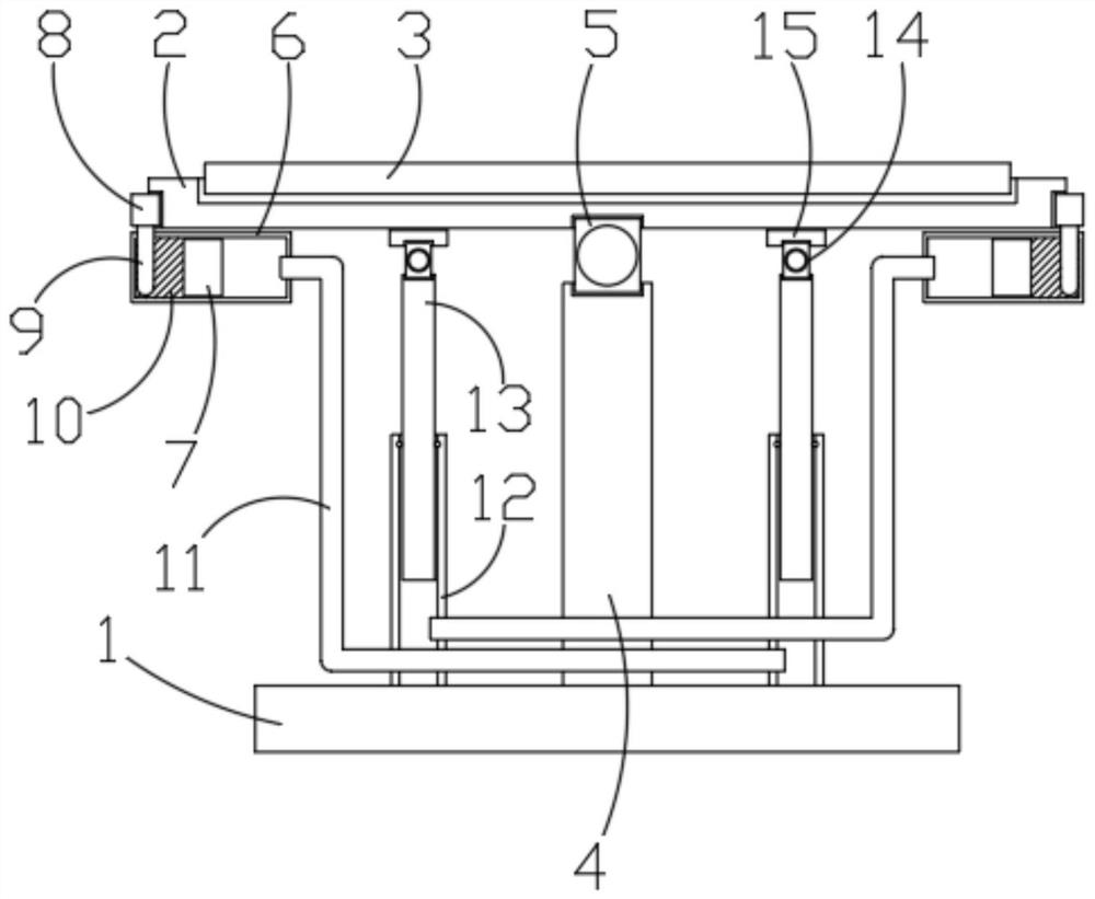
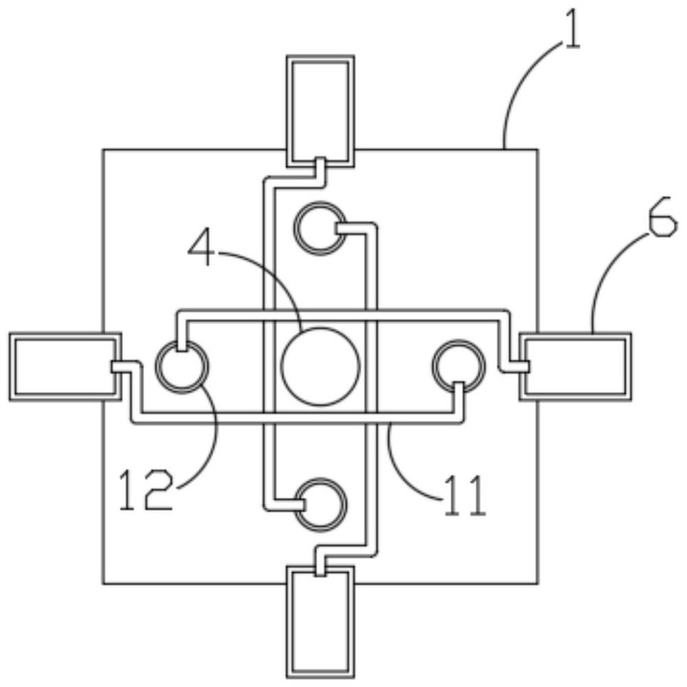
The invention discloses a solar panel mounting bracket capable of self-adaptively adjusting an angle. The solar panel mounting bracket comprises a base; a mounting plate used for mounting a photovoltaic panel, wherein the mounting plate is mounted above the base through a supporting column, one end of the supporting column being fixedly connected with the base, the other end of the supporting column being rotatably connected to the middle of the mounting plate through a first universal joint, the mounting plate is further connected with the base through a plurality of telescopic rods, the lower ends of the telescopic rods being fixedly connected with the base, and the upper ends of the telescopic rods being movably connected with the mounting plate; and driving mechanisms used for controlling the length of the telescopic rods, wherein the number of the driving mechanisms is the same as that of the telescopic rods, the driving mechanisms correspond to the telescopic rods one to one. Each driving mechanism comprises a driving pipe and a heat absorption block, wherein the heat absorption blocks are fixedly installed on the side wall of the mounting plate and make contact with the driving pipes. When the solar panel mounting bracket is not perpendicular to solar rays, the solar panel mounting bracket has the effect of automatically adjusting the angle until the solar panel mountingbracket is perpendicular to the solar rays; and the adjustment accuracy is high, and the power generation efficiency of the solar panel can be exerted to the maximum extent.

Description

technical field [0001] The invention belongs to the technical field of solar panel mounting brackets, in particular to a solar panel mounting bracket for self-adaptive angle adjustment. Background technique [0002] A solar panel module is a power generation device that collects heat when exposed to sunlight and converts light energy into direct current electricity. It is composed of thin solid photovoltaic cells almost entirely made of semiconductor materials (such as silicon). Compared with a solar photovoltaic power generation system at a fixed location, the four seasons of the year are spring, summer, autumn and winter, the sun rises and sunsets every day, and the angle of the sun’s light changes all the time. If the solar panels can always face the sun, the power generation efficiency will reach Best state. [0003] In order to improve the power generation efficiency of solar energy, installation brackets that can automatically adjust the orientation angle of photovolt...

Claims


Application Information

Patent Timeline
Patent Type & Authority Applications(China)
IPC IPC(8): H02S20/32H02S40/42F24S30/48
CPCF24S30/48F24S2030/11H02S20/32H02S40/42Y02E10/47Y02E10/50
Inventor 张东虎
Owner 张东虎
Learn More