Check patentability & draft patents in minutes with Patsnap Eureka AI!

Vehicle control system

A vehicle control system, vehicle technology, applied in the direction of control/regulation systems, vehicle position/route/altitude control, vehicle components, etc.

Pending Publication Date: 2020-10-09
HONDA MOTOR CO LTD
View PDF6 Cites 0 Cited by
  • Summary
  • Abstract
  • Description
  • Claims
  • Application Information

AI Technical Summary

Problems solved by technology

However, in such a vehicle control system, commands from multiple terminals may oppose each other

Method used


Image

  • Vehicle control system
  • Vehicle control system
  • Vehicle control system

Examples


no. 1 approach

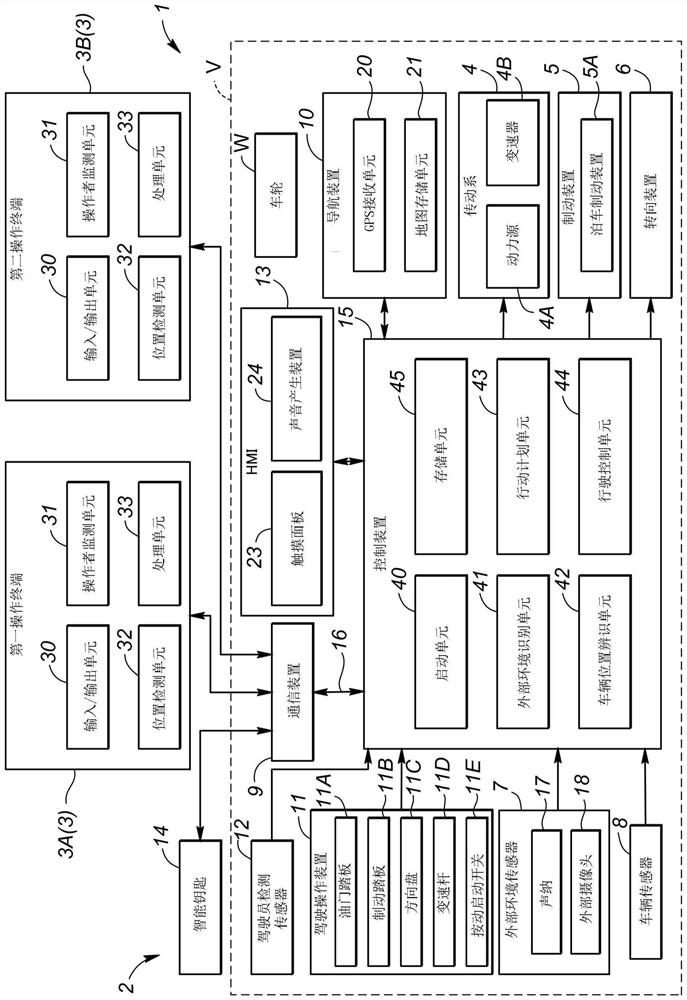
[0026] First, the vehicle control system 1 according to the first embodiment is described. Such as figure 1 As shown in , a vehicle control system 1 includes a vehicle system 2 and a plurality of operation terminals 3 . The vehicle system 2 includes a drive train 4, a braking device 5, a steering device 6, an external environment sensor 7, a vehicle sensor 8, a communication device 9, a navigation device 10, a driving operation device 11, a driver detection sensor 12, an HMI 13, a smart key 14 and control device 15. The above components of the vehicle system 2 are connected to each other by communication means such as a controller area network 16 (CAN), so that signals can be transmitted between the above components. The above components of the vehicle system 2 are mounted to the vehicle V except the smart key 14 .

[0027] The drive train 4 is a device that applies driving force to the vehicle V. As shown in FIG. For example, the drive train 4 includes a power source 4A a...

no. 2 approach

[0086] Such as Figure 6 As shown in , the vehicle control system 101 according to the second embodiment differs from the vehicle control system 1 according to the first embodiment in step ST1 of the terminal authentication process. Further, the vehicle control system 101 according to the second embodiment differs from the vehicle control system 1 according to the first embodiment in that steps ST11 to ST16 are added to the terminal authentication process. The other steps of the terminal authentication process are the same as those in the first embodiment, so description thereof is omitted. In the second embodiment, after the vehicle V is stopped, the control device 15 deletes the activation terminal ID stored in the RAM, and is on standby to wait for a signal from each operation terminal 3 or smart key 14 .

[0087] In step ST11 (the first step of the terminal authentication process), the action planning unit 43 determines whether the vehicle V is operating. At this time, t...


PUM


Abstract

A vehicle control system includes: a plurality of terminals configured to be carried by users; and a control device configured to execute remote parking processing to move a vehicle from a current position to a parking position and to park the vehicle at the parking position in response to an instruction from any of the terminals. The control device is configured to execute starting processing tostart operation of the vehicle in response to the instruction from any of the terminals. Once the control device executes the starting processing in response to an instruction from one of the terminals, the control device prohibits the remote parking processing in response to an instruction from any other of the terminals as long as the vehicle is in operation.

Description

technical field [0001] The invention relates to a vehicle control system for remotely controlling a vehicle by means of multiple terminals. Background technique [0002] A known vehicle control device controls a vehicle by directly operating the vehicle from inside and remotely operating the vehicle via a wireless terminal (for example, Japanese Patent No. 5704178). In this vehicle control device, in a case where commands resulting from these operations are opposed to each other, direct operation of the vehicle from the inside takes precedence over remote operation of the vehicle via the wireless terminal. [0003] A vehicle control system for remotely controlling a vehicle may be provided with a plurality of terminals capable of remotely controlling a vehicle. However, in such a vehicle control system, commands from a plurality of terminals may oppose each other. Contents of the invention [0004] In view of such problems of the prior art, a main object of the present i...

Claims


Application Information

Patent Timeline
IPC IPC(8): B60W30/06
CPCB60W30/06B60N2210/24B60N2/003B60N2210/12B60N2230/20B60N2/0024G05D1/0022B62D15/0285B62D1/00G05D1/0016G05D1/021B60N2/002
Inventor 野口顺平小和田正浩辻野美树
Owner HONDA MOTOR CO LTD
Features
  • R&D
  • Intellectual Property
  • Life Sciences
  • Materials
  • Tech Scout
  • Unparalleled Data Quality
  • Higher Quality Content
  • 60% Fewer Hallucinations
Learn More