Scanning display method and device

A display device and display method technology, applied to static indicators, instruments, optical fiber transmission, etc., to achieve the effect of improving image display capabilities

Active Publication Date: 2020-10-09
CHENGDU IDEALSEE TECH
View PDF21 Cites 2 Cited by
  • Summary
  • Abstract
  • Description
  • Claims
  • Application Information

AI Technical Summary

Problems solved by technology

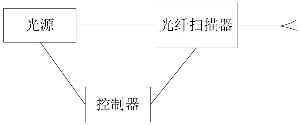
[0005] The purpose of the embodiment of the present invention is to provide a scanning display method and device to solve the technical problem of the scanning display effect of the scanning display device in the prior art

Method used


Image

  • Scanning display method and device
  • Scanning display method and device
  • Scanning display method and device

Examples


Embodiment Construction

[0032] First of all, the term "and" in the embodiment of the present invention is just a kind of relationship describing the relationship between related objects, which means that there can be three kinds of relationships, for example, A and B, which can mean: A exists alone, A and B exist simultaneously, and A and B exist alone. There are three cases of B. In addition, the character " / " in this article generally indicates that the contextual objects are an "or" relationship.

[0033] When the present invention refers to ordinal numerals such as "first", "second", "third" or "fourth", unless it really expresses the meaning of order according to the context, it should be understood as only for distinction.

[0034] The following will clearly and completely describe the technical solutions in the embodiments of the present invention in conjunction with the accompanying drawings in the embodiments of the present invention. Obviously, the described embodiments are only some of the...


PUM


Abstract

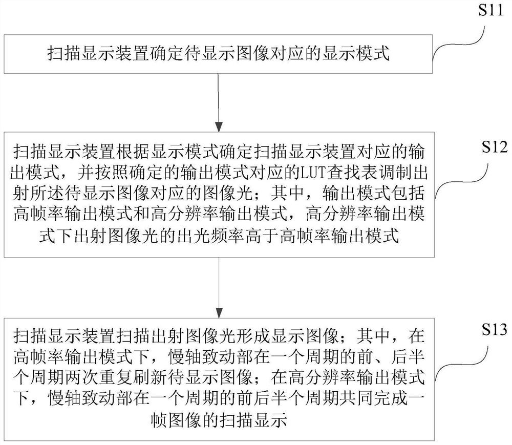
The embodiment of the invention provides a scanning display method and device. The scanning display method and device are used for improving the scanning display capacity of a scanning display device.The method comprises the steps of determining a display mode corresponding to a to-be-displayed image; determining an output mode corresponding to the scanning display device according to the displaymode, and controlling the light source to modulate and emit image light corresponding to the to-be-displayed image according to an LUT lookup table corresponding to the determined output mode, wherein the output mode comprises a high-frame-rate output mode and a high-resolution output mode; scanning and emitting the image light through an optical fiber scanner to form a display image, wherein inthe high-frame-rate output mode, the slow-axis actuating part refreshes the image to be displayed repeatedly twice in the first half period and the second half period of one period, and in the high-resolution output mode, the slow-axis actuating part completes scanning display of one frame of image in the first half period and the second half period of one period.

Description

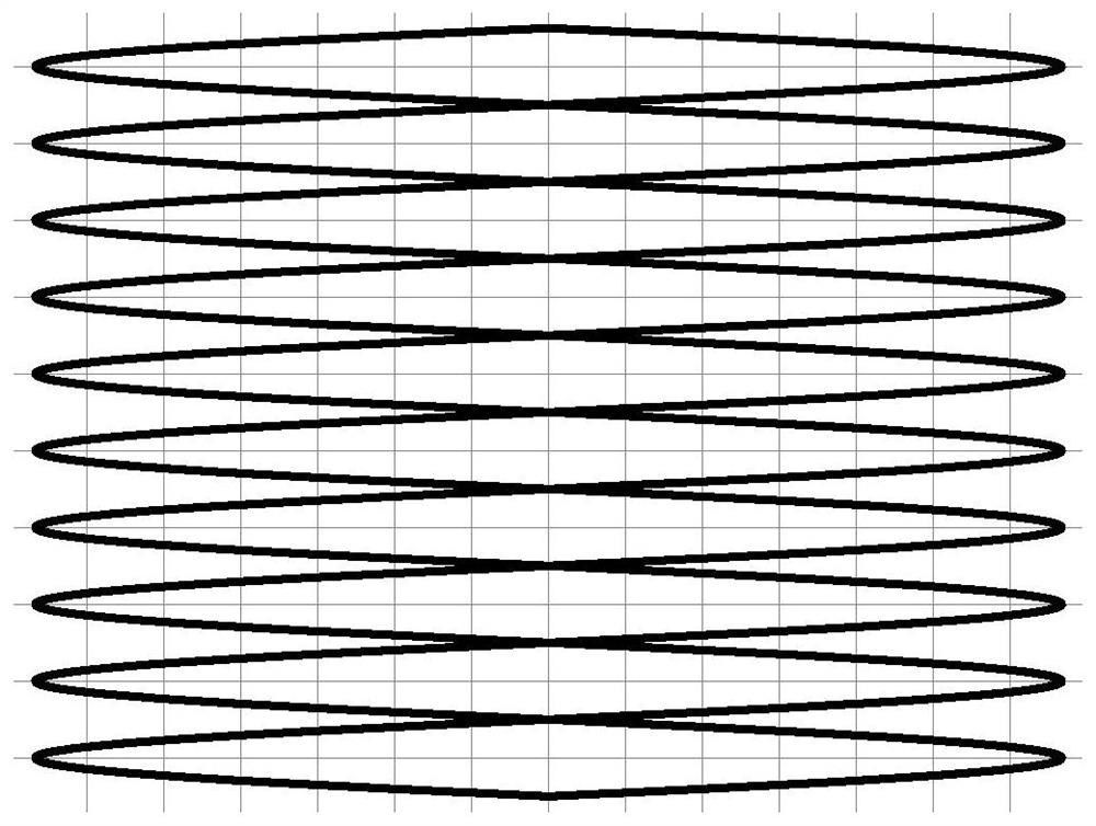
technical field [0001] The invention relates to the field of display technology, in particular to a scanning display method and device. Background technique [0002] The main structure of the current fiber optic scanner is composed of a base, an actuator, an optical fiber, and a lens. A part of the optical fiber is fixed on the actuator, and a part extends out of the actuator as a fiber cantilever. When working, the actuator has one end fixed to the base as the fixed end, and the other end as the free end; the actuator has two independent vibration directions, and the sweeping trajectory of the free end is the composite trajectory of the two independent vibration directions; the optical fiber The cantilever is then driven to scan, and the end of the fiber cantilever scans in a trajectory such as a spiral or propeller, Lissajous, or grid. [0003] In the technology of the grid scanning method, the actuator is composed of a first actuating part vibrating in a first direction ...

Claims


Application Information

Patent Timeline
Patent Type & Authority Applications(China)
IPC IPC(8): G02B26/10H04B10/516H04B10/25G09G3/00
CPCG02B26/103H04B10/516H04B10/25G09G3/001
Inventor 不公告发明人
Owner CHENGDU IDEALSEE TECH
Why Eureka
Try Eureka