
Pixel circuit and driving method thereof, organic light-emitting display panel and display apparatus

A pixel circuit and organic technology, applied in the field of organic light-emitting display panels and display devices, can solve the problems of not affecting LCD display characteristics, difficult to overcome the problems of collecting touch signals, affecting the image display effect, etc., so as to improve the image display effect and eliminate the Affect and improve the effect of uniformity

Active Publication Date: 2014-09-03
BOE TECH GRP CO LTD +1
View PDF8 Cites 30 Cited by
  • Summary
  • Abstract
  • Description
  • Claims
  • Application Information

AI Technical Summary

Problems solved by technology

Due to the process and device aging, the threshold voltage (Vth) of the driving thin film transistor of each pixel will drift, which will cause the current flowing through each pixel OLED to change due to the change of the threshold voltage, making the display brightness not stable. uniform, thus affecting the display effect of the entire image
[0004] At present, on the LCD monitors where the in-cell touch technology has been applied, the more commonly used in-cell touch technology includes capacitive touch in-cell technology, and the most difficult technical problem to solve for the in-cell touch in-cell technology at present is the problem of signal interference, that is, touch There is a considerable parasitic capacitance between the electrodes and the electrodes required for the LCD to work, so it is difficult to overcome the problem of smoothly collecting touch signals without affecting the display characteristics of the LCD itself.

Method used


Image

  • Pixel circuit and driving method thereof, organic light-emitting display panel and display apparatus
  • Pixel circuit and driving method thereof, organic light-emitting display panel and display apparatus
  • Pixel circuit and driving method thereof, organic light-emitting display panel and display apparatus

Examples


Embodiment Construction

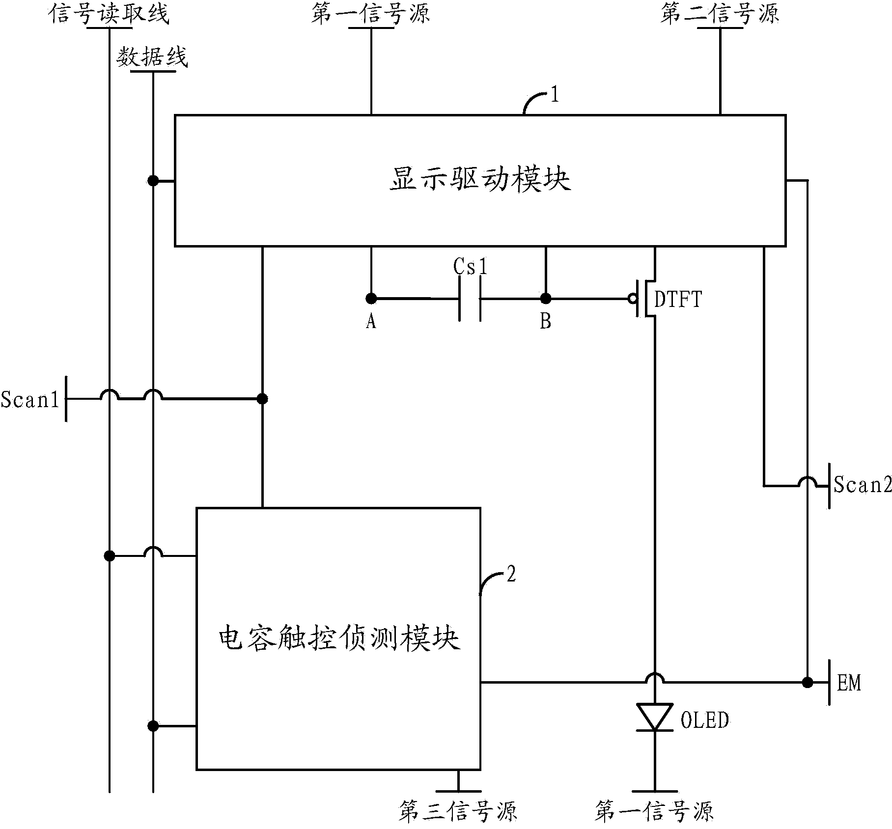
[0068] In order to make the purpose, technical solutions and advantages of the embodiments of the present invention more clear, the following will clearly and completely describe the technical solutions of the embodiments of the present invention in conjunction with the drawings of the embodiments of the present invention. Apparently, the described embodiments are some, not all, embodiments of the present invention. All other embodiments obtained by those skilled in the art based on the described embodiments of the present invention belong to the protection scope of the present invention.

[0069] Unless otherwise defined, the technical terms or scientific terms used herein shall have the usual meanings understood by those skilled in the art to which the present invention belongs. "First", "second" and similar words used in the patent application specification and claims of the present invention do not indicate any order, quantity or importance, but are only used to distinguis...


PUM


Abstract

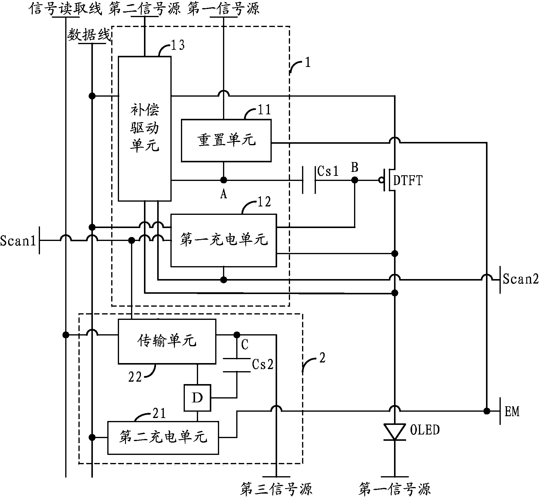
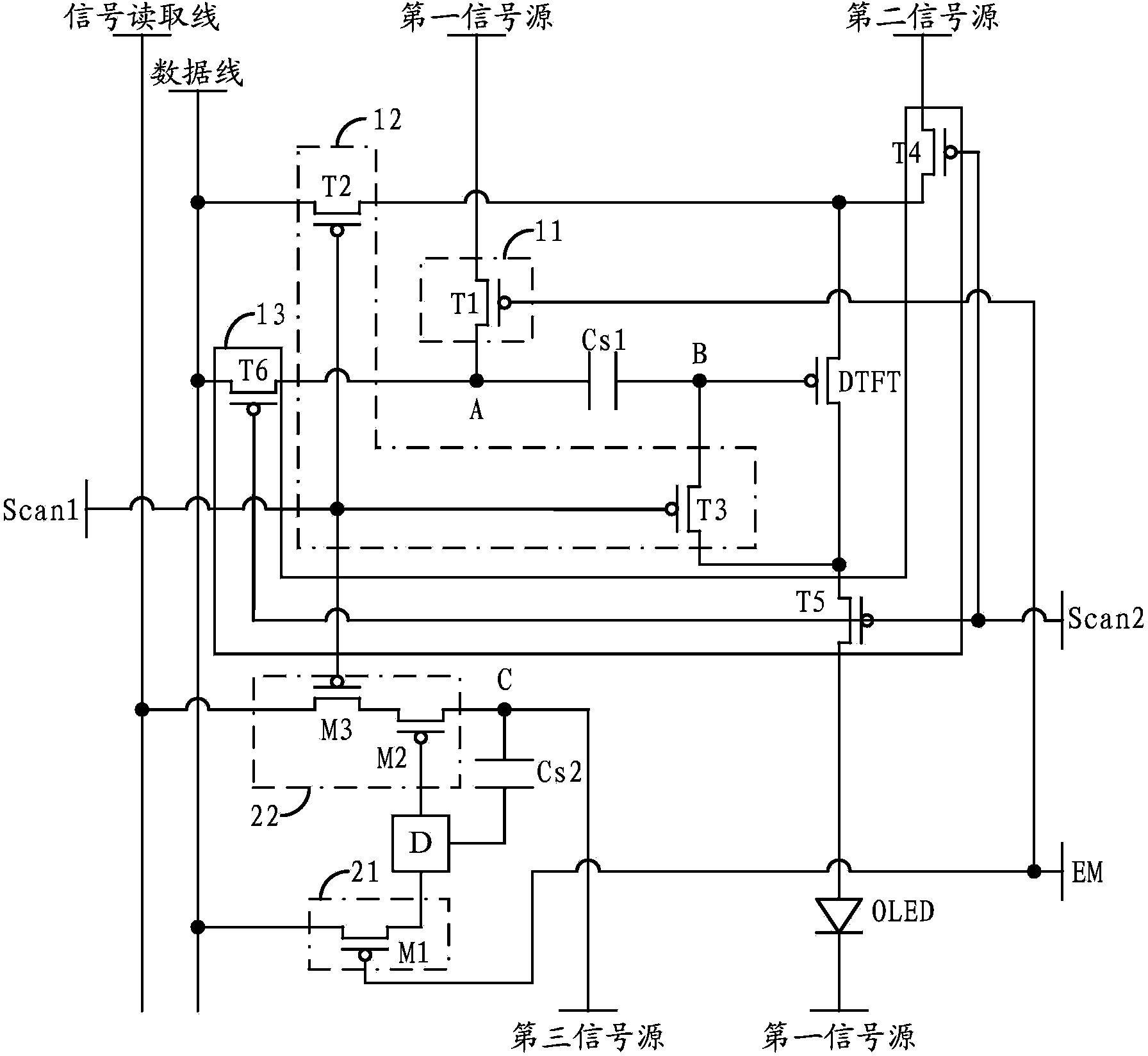
The invention provides a pixel circuit and a driving method thereof, an organic light-emitting display panel and a display apparatus. The pixel circuit comprises a display driving module and a capacitor touch control detection module, wherein the display driving module is used for performing compensation processing on driving transistor threshold voltages under the control of a first scanning signal input by a first scanning line, a second scanning signal input by a second scanning line and a control signal input by a control line by use of a data signal input by a data line and a second signal input by a second signal source within a certain time period so as to enable the light-emitting driving signal of an organic light-emitting diode to be irrelevant with the driving transistor threshold voltages within a third phase of the time period; and the capacitor touch control detection module is used for detecting a touch signal of a touch screen within the time period under the control of the first scanning signal and the control signal. According to the invention, the image display effect of a display apparatus is improved and high-efficiency integration of display driving and touch control detection is realized.

Description

technical field [0001] The present invention relates to the field of display technology, in particular to a pixel circuit and a driving method thereof, an organic light-emitting display panel and a display device. Background technique [0002] Organic light-emitting display (AMOLED) is one of the hotspots in the field of flat panel display research. Compared with liquid crystal display, organic light-emitting diode (OLED) has the advantages of low energy consumption, low production cost, self-illumination, wide viewing angle and fast response speed. , OLED has begun to replace the traditional liquid crystal display (LCD) in display fields such as mobile phones, PDAs, and digital cameras. Pixel drive circuit design is the core technical content of AMOLED display, which has important research significance. [0003] Unlike TFT-LCD, which uses a stable voltage to control brightness, OLED is current-driven and requires a stable current to control light emission. Due to the proc...

Claims


Application Information

Patent Timeline
Patent Type & Authority Applications(China)
IPC IPC(8): G09G3/32G06F3/044G09G3/325
CPCG06F3/0412G06F3/04184G06F3/044G09G3/3233G09G2300/0819G09G2300/0852G09G2300/0861G06F2203/04111G09G3/3266G09G3/3275G09G2320/0626
Inventor 杨盛际
Owner BOE TECH GRP CO LTD
Learn More