Display control device of liquid crystal panel and liquid crystal display device

Active Publication Date: 2005-05-17
SHARP KK
View PDF7 Cites 29 Cited by
  • Summary
  • Abstract
  • Description
  • Claims
  • Application Information

AI Technical Summary

Benefits of technology

[0025]The first and second operational units correct the exceeded display data and the target display data according to the rate correcting values which are output from the rate memory unit corresponding to the frame rate d

Problems solved by technology

Consequently, in displaying moving images in particular, blurs in which data of previous frames appears overlapped (image trails) tend to occur.
This results in a higher propensity to new trails, sometime

Method used


Image

  • Display control device of liquid crystal panel and liquid crystal display device
  • Display control device of liquid crystal panel and liquid crystal display device
  • Display control device of liquid crystal panel and liquid crystal display device

Examples


first embodiment

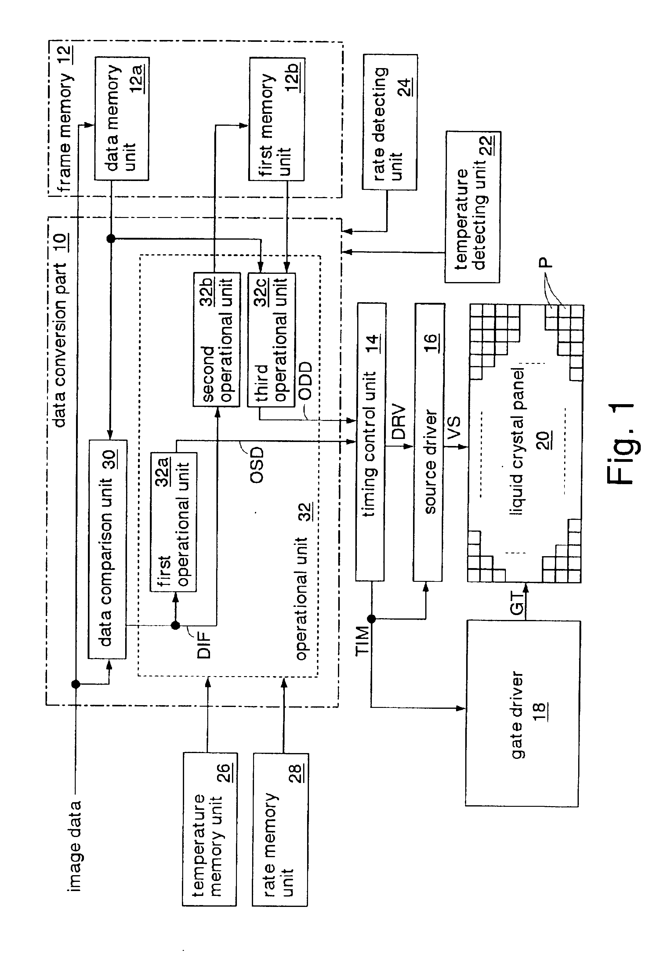
[0037]FIG. 1 shows the display control device of a liquid crystal panel and the liquid crystal display device according to the present invention.

[0038]The liquid crystal display device comprises a data conversion part 10, a frame memory 12, a timing control unit 14, a source driver 16, a gate driver 18, a liquid crystal panel 20, a temperature detecting unit 22, a rate detecting unit 22, a temperature memory unit 26, and a rate memory unit 28. The data conversion part 10, frame memory 12, timing control unit 14, source driver 16, gate driver 18, temperature detecting unit 22, rate detecting unit 24, temperature memory unit 26, and rate memory unit 28 function as a display control device for displaying images on the liquid crystal panel.

[0039]The liquid crystal display device of this embodiment operates on hold drive. That is, data signals corresponding to the same image data are supplied to the liquid crystal cells over a period of one frame (16.6 ms) for displaying a single frame o...

third embodiment

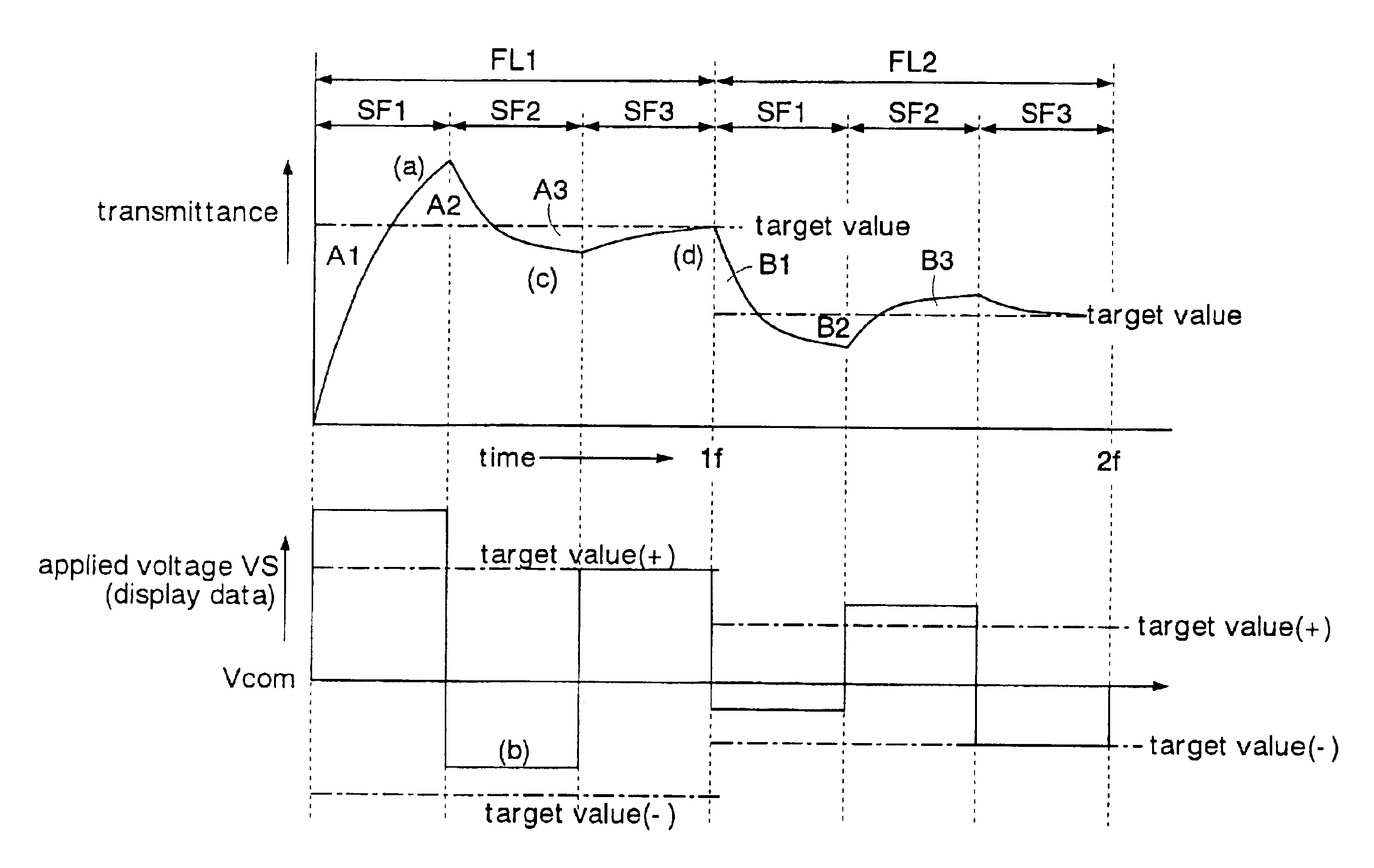
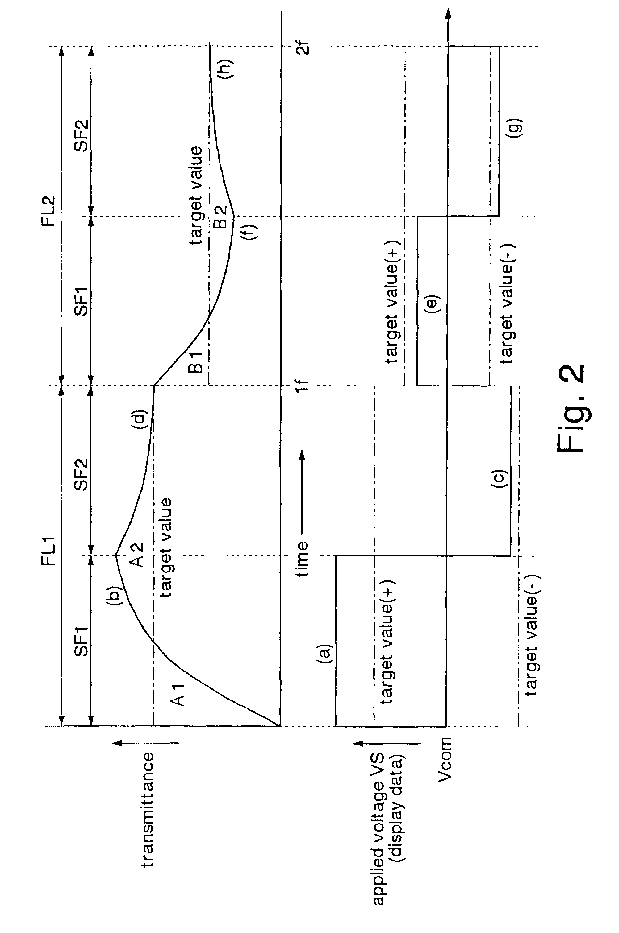
[0086]FIG. 7 shows how a single pixel (liquid crystal cell) of the liquid crystal panel is written with data in the liquid crystal display device of the In this example, image data to increase the transmittance (e.g., data to increase luminance) is supplied for a frame period FL1, and image data to decrease the transmittance (e.g., data to decrease luminance) is supplied for a frame period FL2. Even in the present embodiment, the same operation as what is called frame inversion driving is performed. The applied voltage VS corresponds to the display data OSD1, OSD2, and ODD output from the operational unit 36 shown in FIG. 6. In the following description, the levels of the applied voltage VS refer to the absolute values of the applied voltage VS.

[0087]Initially, in the first subfield SF1 of the frame period FL1, an overshoot operation is performed as in the first embodiment, according to the exceeded display data OSD1. The transmittance of the liquid crystal cell goes up and exceeds...


PUM


Abstract

An operational unit determines, for subfield(s) other than a last subfield of a plurality of subfields constituting a single frame period, based on a difference determined by a data comparison unit, exceeded display data for setting the transmittance of each pixel to a value exceeding a target transmittance corresponding to image data supplied anew. The operational unit also determines, for the last subfield of the single frame period, based on the difference determined by the data comparison unit, target display data for setting the transmittance of each pixel to the target transmittance. An overshoot operation or operations are performed within the single frame period, and each pixel is set to the transmittance corresponding to the image data. This makes it possible to avoid trails occurring in moving image display and enhance the appearance of moving image display with no increase in frame rate.

Description

BACKGROUND OF THE INVENTION[0001]1. Field of the Invention[0002]The present invention relates to a display control device of a liquid crystal panel for controlling display data to be displayed on the liquid crystal panel, and a liquid crystal display device.[0003]2. Description of the Related Art[0004]Liquid crystal display devices are low in power consumption and compact in size, and thus are widely adopted in personal computers, television sets, and so on. In a liquid crystal display device, an electric field applied to each liquid crystal cell (pixel) of the liquid crystal panel is adjusted to change the transmittance of the liquid crystal cell for image display. Liquid crystal cells vary in transmittance relatively slowly. Consequently, in displaying moving images in particular, blurs in which data of previous frames appears overlapped (image trails) tend to occur. This phenomenon is unique to liquid crystal display devices, not seen in CRTs (Cathode Ray Tubes).[0005]To reduce t...

Claims


Application Information

Patent Timeline
IPC IPC(8): G02F1/133G02F1/13G09G3/36G09G3/20H04N5/66
CPCG09G3/3685G09G3/2022G09G2340/16G09G2320/0252G09G2320/041G09G2310/06G02F1/133
Inventor SUZUKI, TOSHIAKIKATAGAWA, KOICHIYONEMURA, KOSHUKOJIMA, TOSHIHIROYUDA, TAKASHI
Owner SHARP KK
Why Eureka
Try Eureka