Organic electroluminescent screen body and preparation method thereof

An electroluminescence screen and luminescence technology, which is applied in the field of OLED devices, can solve the problems of reduced aperture ratio, current difference, uneven distribution of electrode wiring resistance inside the screen, etc., and achieve the path of increasing edge erosion and optimizing Encapsulation performance, the effect of improving the stability of the screen body

Pending Publication Date: 2020-10-09
GUAN YEOLIGHT TECH CO LTD
View PDF8 Cites 0 Cited by
  • Summary
  • Abstract
  • Description
  • Claims
  • Application Information

AI Technical Summary

Problems solved by technology

But this way of thinking brings the following new problems: pixelated design brings about lower aperture ratio and more complex process, higher continuous picture requirements require higher number of pixels (high resolution), circuit control becomes unusually complex etc.
[0005] figure 1 It is an equivalent circuit diagram of an OLED light-emitting screen in the prior art. Due to the shape of the screen, the electrode material, the organic charge transport material, and the non-uniform distribution of the resistance of the electrode wiring inside the screen (due to uneven line width, thickness, etc.), Influenced by many factors such as uneven distribution of charge transmission inside the screen (inhomogeneous evaporation thickness and concentration), the uniform distribution of light emission of the screen has always been a problem that plagues the manufacture and use of OLEDs. The input current is transmitted to the equivalent light-emitting diode unit , the actual current varies greatly

Method used


Image

  • Organic electroluminescent screen body and preparation method thereof
  • Organic electroluminescent screen body and preparation method thereof
  • Organic electroluminescent screen body and preparation method thereof

Examples


Embodiment 1

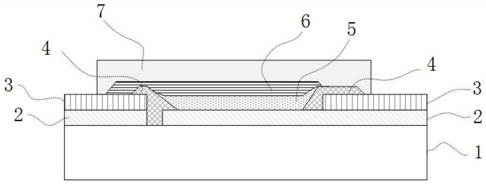
[0055] Such as image 3 As shown, the organic electroluminescent screen provided by the present invention includes: a screen substrate 1, an anode 2, an auxiliary electrode 3, an insulating layer 4, an organic functional layer 5, a cathode 6, an encapsulation layer 7, and the like.

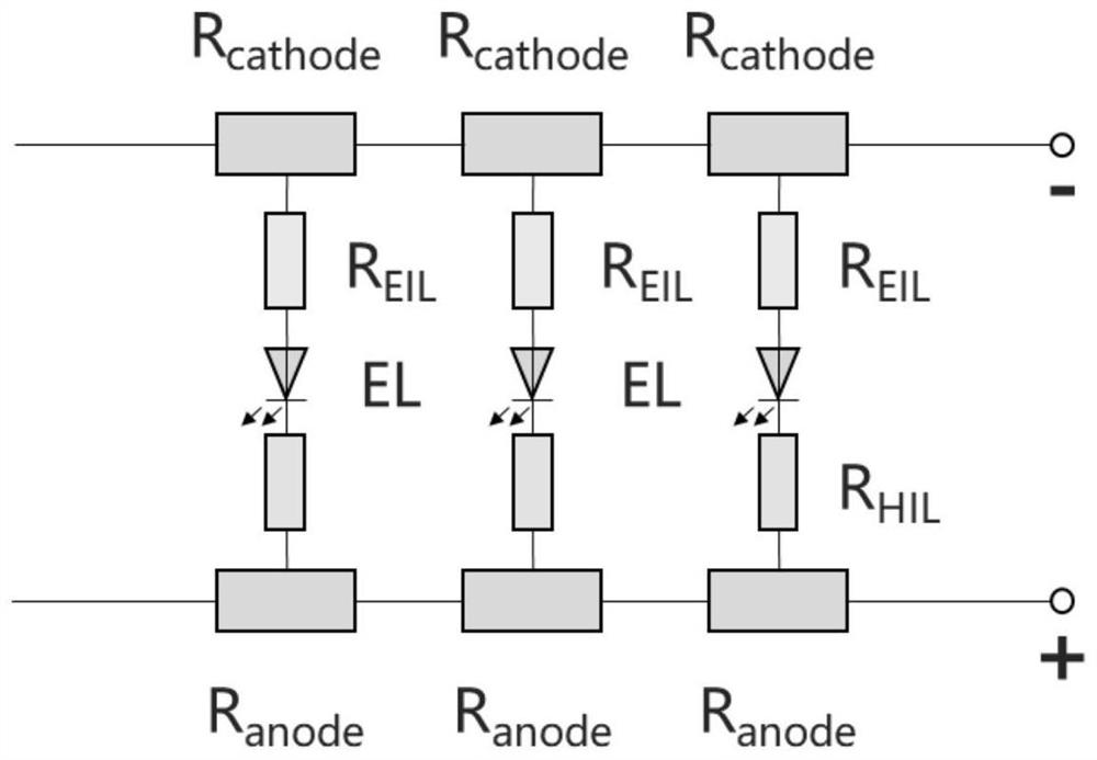
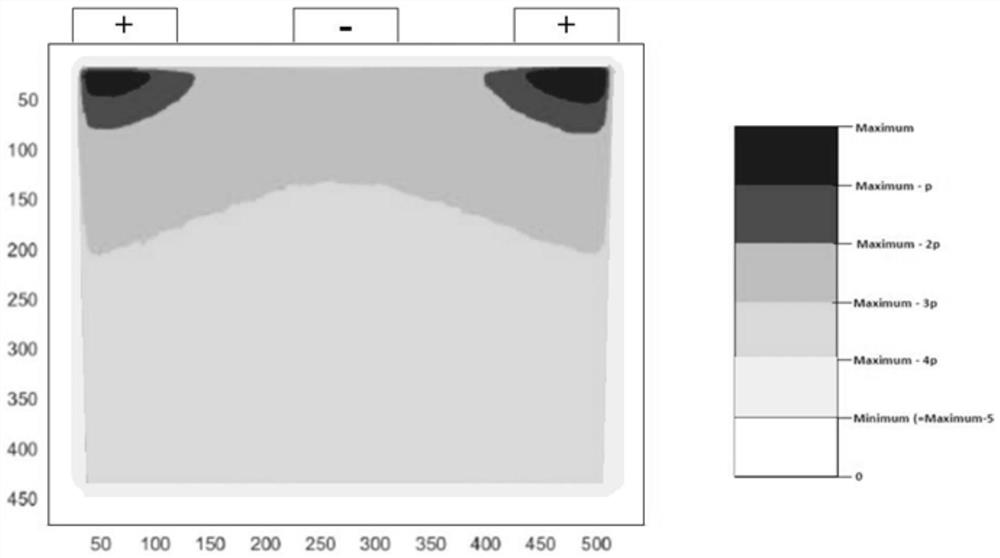
[0056] Such as Figure 4 As shown, when only #1 electrode injects current, the equivalent organic light-emitting diode close to the electrode will obtain higher current. As the resistance value increases or the resistance value distribution is uneven, the luminous brightness of the area far away from #1 will be different. decline. For this reason, the present invention can increase the uniformity of the remote equivalent light emitting diode by introducing a new electrode #2.

[0057] Such as Figure 5 to Figure 11 As shown, the present invention provides an organic electroluminescent screen body. One or more injection electrodes are bound around the OLED screen body. The corresponding electro...

Embodiment 2

[0060] Such as Figure 5 Shown is the organic electroluminescent screen body provided by the present invention with injection electrodes bound on the same edge. Along the edge position of the light-emitting area 13 of the OLED screen body, i anode electrodes 9 and one cathode electrode 8 are provided. The screen body The four edge positions of the light-emitting area are distributed with anode partial inflow areas, which is more convenient for brightness adjustment of the screen light-emitting area; of course, the anode partial inflow areas can also be distributed in two or three of the edge positions of the screen light-emitting area . Wherein the lead wire 11 of the light-emitting area of ​​the anode local inflow region can be a lead wire 11 of the light-emitting area of ​​different shapes or a whole anode or an anode and an auxiliary electrode, such as Figure 6 As shown, lead wires of different shapes can change the resistance value of a single lead wire, thereby changing...

Embodiment 3

[0062] Such as Figure 7 As shown, i anode electrodes 9 are arranged at the four edge positions of the light-emitting area 13 of the square OLED panel, and the method of directly binding the anode electrodes on the sides of the screen is adopted, and a cathode electrode 8 is shared.


PUM


Abstract

The invention discloses an organic electroluminescent screen body and a preparation method thereof. One or more injection electrodes are bound to the periphery of the OLED screen body, electrically connected with corresponding electrode inflow areas arranged in a light-emitting area of the OLED screen body through light-emitting area leads or connecting wires and used for inputting currents into all local light-emitting areas in the OLED screen body. According to the invention, independent current control can be carried out on each injection electrode or a plurality of different injection electrodes, so that the purpose of controlling screen body brightness distribution is achieved. According to the preparation method provided by the invention, the screen body brightness imbalance area canbe searched, the control of the light-emitting uniformity distribution of the light-emitting area of the OLED screen body is realized by adjusting the current input of the injection electrode. The problem of uneven brightness distribution caused by difference of actual current input of each local light-emitting area in the light-emitting area of the OLED screen body is solved, and the OLED screenbody brightness compensation method can be applied to ex-factory detection to perform brightness compensation on the screen body without TFT control.

Description

technical field [0001] The invention relates to the technical field of OLED devices, in particular to an organic electroluminescence screen body and a preparation method thereof. Background technique [0002] OLED light-emitting screen body, because it is a current-driven light-emitting device, the luminous intensity is proportional to the size of the current injection. In order to obtain the change of the real picture, PM or AM-TFT two driving methods are generally used for fine control of pixelation. [0003] Both PM and AM-TFT driving methods are based on the concept of independent pixelation to control the real picture or brightness. But this way of thinking brings the following new problems: pixelated design brings about lower aperture ratio and more complex process, higher continuous picture requirements require higher number of pixels (high resolution), circuit control becomes Extremely complex etc. [0004] For general light sources, in order to improve the overal...

Claims


Application Information

Patent Timeline
IPC IPC(8): H01L51/52H01L27/32H05B45/00H05B45/30
CPCH05B45/60H05B45/30H10K59/10H10K50/81H10K50/82Y02B20/30
Inventor 许显斌李栋栋陈旭
Owner GUAN YEOLIGHT TECH CO LTD
Why Eureka
Try Eureka