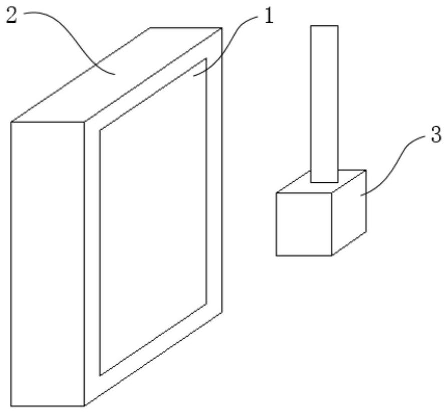
Cabinet door and monitoring system

A cabinet door and cabinet body technology, applied in the direction of windows/doors, door/window applications, special equipment for doors/windows, etc., can solve the problem of frame blocking the points to be inspected, poor sealing between cabinet doors and cabinet bodies, and low installation efficiency And other issues

Active Publication Date: 2020-10-09
SHENZHEN POWER SUPPLY BUREAU
View PDF14 Cites 0 Cited by
  • Summary
  • Abstract
  • Description
  • Claims
  • Application Information

AI Technical Summary

Problems solved by technology

However, the connection structure between the horizontal frame and the vertical frame in the cabinet door frame is distributed on the side of the cabinet door, which reduces the matching degree between the side of the cabinet door and the door frame of the cabinet body, resulting in poor sealing between the cabinet door and the cabinet body, and reducing the dustproof performance. Effect
The connection structure is relatively complicated, which makes it difficult to install the transparent panel and the frame, and the installation efficiency is low
In addition, in order to ensure the stability of the connection, a sufficiently large paste area is required to ensure the stability of the connection, and then the size of the frame needs to be designed larger, and the larger size will cause the frame to block some of the points to be checked, resulting in visual effects not ideal

Method used


Image

  • Cabinet door and monitoring system
  • Cabinet door and monitoring system
  • Cabinet door and monitoring system

Examples


Embodiment Construction

[0040] In order to make the above objects, features and advantages of the present invention more comprehensible, specific implementations of the present invention will be described in detail below in conjunction with the accompanying drawings. In the following description, numerous specific details are set forth in order to provide a thorough understanding of the present invention. However, the present invention can be implemented in many other ways different from those described here, and those skilled in the art can make similar improvements without departing from the connotation of the present invention, so the present invention is not limited by the specific embodiments disclosed below.

[0041] In describing the present invention, it should be understood that the terms "center", "longitudinal", "transverse", "length", "width", "thickness", "upper", "lower", "front", " Back", "Left", "Right", "Vertical", "Horizontal", "Top", "Bottom", "Inner", "Outer", "Clockwise", "Counte...


PUM


Abstract

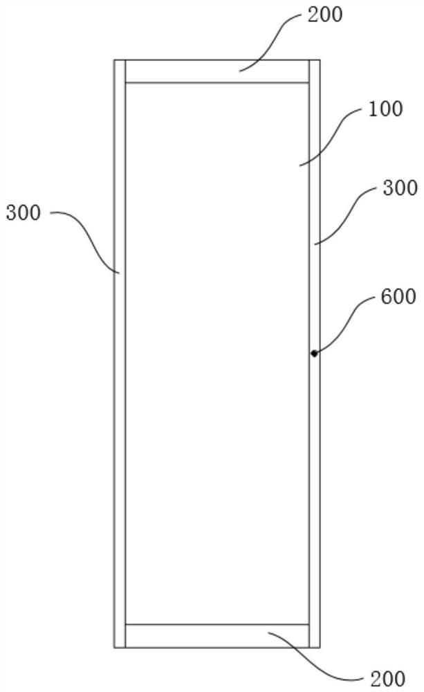
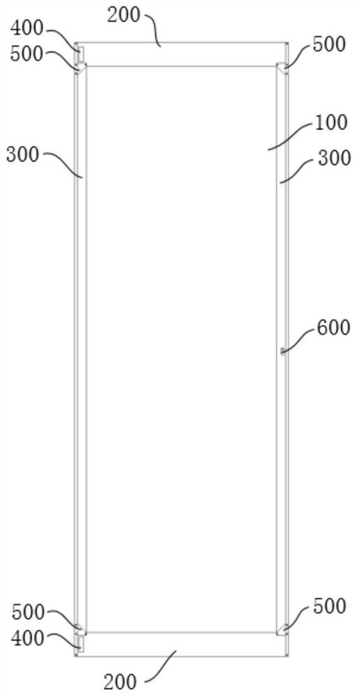
The invention relates to a cabinet door and a monitoring system, and the cabinet door comprises: a transparent panel which covers the surface of a target region of a cabinet body; a horizontal frame which is clamped to the upper edge and the lower edge of the transparent panel through first necks, wherein in the vertical frame, a first clamping plate abuts against the side face of the transparentpanel and the inner surface of a second side wall, the first clamping plate extends to form a second clamping plate, and the second clamping plate abuts against the outer surface of the transparent panel and the end face of the first side wall; an abutting plate which is fixedly connected with the first clamping plate, abuts against the end face of the second side wall and extends along the outersurface of the second side wall to form a third clamping plate, and the third clamping plate abuts against the outer surface of the second side wall; and a first connecting piece which is connected with the horizontal frame and the vertical frame. According to the cabinet door, stable connection of the vertical frame and the horizontal frame is achieved, the stability is improved, the connecting pieces are simplified, the dustproof performance is improved, and the visual blind area is reduced.

Description

technical field [0001] The invention relates to the technical field of equipment monitoring, in particular to a cabinet door and a monitoring system. Background technique [0002] The operation surface of the instrument in the substation is often covered with a cabinet door for dust prevention, and a cabinet door with a transparent panel pasted on the frame is often used. However, the connection structure between the horizontal frame and the vertical frame in the cabinet door frame is distributed on the side of the cabinet door, which reduces the matching degree between the side of the cabinet door and the door frame of the cabinet body, resulting in poor sealing between the cabinet door and the cabinet body, and reducing the dustproof performance. Effect. The connection structure is relatively complicated, which makes it difficult to install the transparent panel and the frame, and the installation efficiency is low. In addition, in order to ensure the stability of the co...

Claims


Application Information

Patent Timeline
Patent Type & Authority Applications(China)
IPC IPC(8): H02B7/06H02B1/28H02B1/30H02B1/38E06B5/00E06B7/28E06B7/16
CPCH02B7/06H02B1/28H02B1/30H02B1/38E06B5/00E06B7/28E06B7/16
Inventor 吴力飚邵心元徐娟郑庆梦薛志成崔志文王宏陈旭谌兆敏刘涛马小军陈佳鹏陈学有钟田勇马鲁彦
Owner SHENZHEN POWER SUPPLY BUREAU
Why Eureka
Try Eureka