Electric bicycle hub motor with gear protection mechanism

A technology for electric bicycles and protection mechanisms, which is applied to synchronous motors with stationary armatures and rotating magnets, gear transmissions, electromechanical devices, etc., and can solve the problems of manual coil winding, short mileage, broken teeth of planetary gears, etc. problem, to achieve the effect of solving the problem of gear broken teeth, improving the torque bearing capacity, and increasing the mileage

Pending Publication Date: 2020-10-09
眭华兴
View PDF3 Cites 0 Cited by
  • Summary
  • Abstract
  • Description
  • Claims
  • Application Information

AI Technical Summary

Problems solved by technology

[0002] Existing electric bicycles have geared hub motors, such as the Chinese patents CN03127256.8 and CN201510104597.9 of the outer rotor motor with a through-shaft structure, and the US patent US20050176542A1 of the inner rotor motor with a half shaft structure. It is a DC permanent magnet motor with a radial magnetic field. This type of high-efficiency range is biased towards the high-power range. When the vehicle is running normally, the drive motor usually runs in the low-efficiency range, and the driving mileage is short; and the efficiency platform range is wide, which can greatly improve the continuation. Mileage's ironless axial magnetic field has a gear hub motor, which needs to consume more rare earth permanent magnets, and its economy is obviously insufficient. The axial magnetic field motor with a stator core wound by continuous punching of silicon steel sheets, the stator core The manufacturing efficiency is high and the cost is high. The coil winding can only be completed manually at present, and the cost of mass production is relatively high.
The above geared hub motors all adopt the structure of a planetary gear reduction mechanism. The planetary gears are made of polymer materials such as nylon or polyoxymethylene with good wear resistance and self-lubricating properties. When the electric bicycle starts / brakes, the deceleration The gears of the mechanism have to bear a large impact force, and the planetary gears with low structural strength will have broken teeth. This phenomenon is more likely to occur in the cold winter, and the market acceptance is not high

Method used


Image

  • Electric bicycle hub motor with gear protection mechanism
  • Electric bicycle hub motor with gear protection mechanism
  • Electric bicycle hub motor with gear protection mechanism

Examples


Embodiment 1

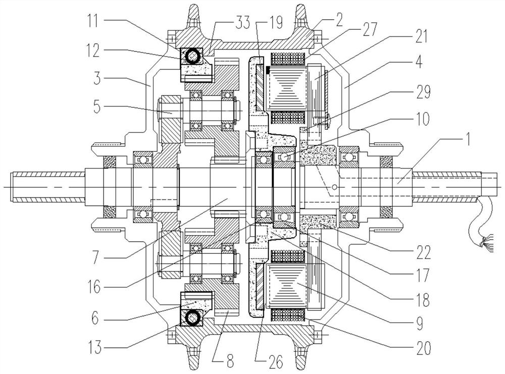
[0041] The stator core 9 with two first mortise grooves 23 of "U" shape is connected with the stator tray 22 sleeved with the stator yoke plate 21 in a mortise and tenon structure:

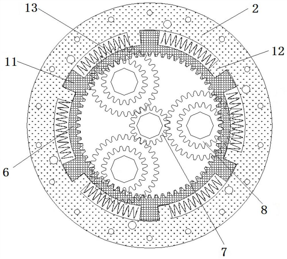
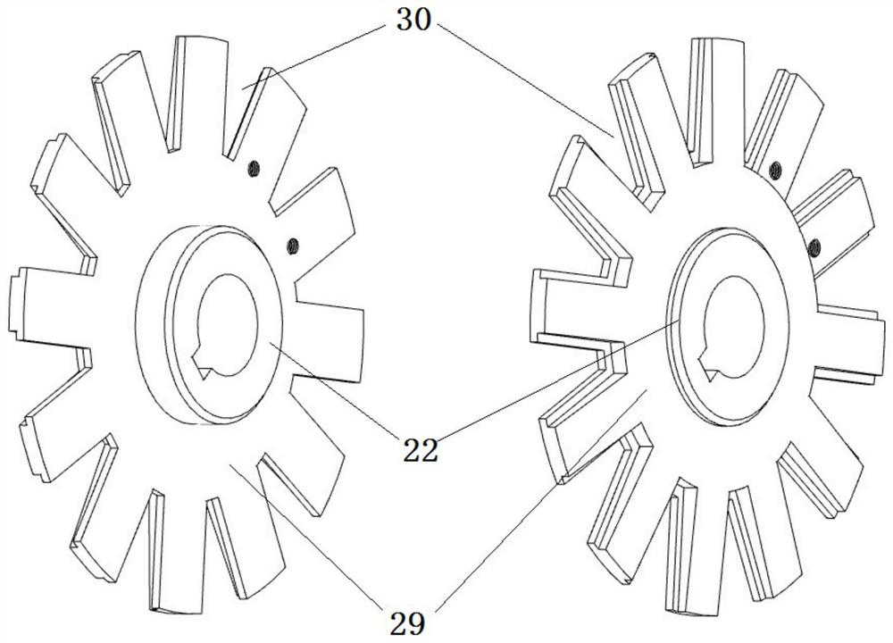
[0042] Such as image 3 , Figure 4 As shown, the first mortise 23 is a "U"-shaped groove, and the stator yoke disk 21 formed by stacking a plurality of silicon steel rings along the axial direction is provided with a circumferential array arrangement connected to the stator core 9. The matched second mortise 28, the end of the stator tray 22 away from the rotor disk 18 has a radial tray 29, and the radial tray 29 is provided with a third mortise 30 connected to the stator core 9 and corresponding to the second mortise 28, The groove shapes of the second mortise 28 and the third mortise 30 correspond to the solid part between the two first mortises 23, and the groove width of the first mortise 23 is consistent with the axial direction of the stator yoke plate 21 and the stator tray 22. The sum o...

Embodiment 2

[0045] The stator core 9 with two first mortise grooves 23 which are "U"-shaped grooves is connected with the stator yoke plate 21 in a mortise and tenon structure:

[0046] The first mortise 23 is a "U"-shaped groove, and the stator yoke plate 21 is provided with a second mortise 28 arranged in a circumferential array to connect and cooperate with the stator core 9. The second mortise 28 is an open groove, and the stator yoke plate 21 The side near the main shaft 1 is also provided with several first connection holes 31 fixedly connected with the stator tray 22; the stator tray 22 has a radial tray 29 at one end close to the rotor disk 18, and the radial tray 29 is provided with the first connection holes. 31 corresponds to the second connecting hole 32, the stator yoke plate 21 is sleeved on the stator tray 22, through the first connecting hole 31 and the second connecting hole 32, fixedly connected by riveting or bolting process; the second connecting hole of the stator yoke...

Embodiment 3

[0049] The stator core 9 whose first mortise 23 is a "U"-shaped groove is connected with the stator yoke 21 with a reinforcing disk 25 in a mortise and tenon structure:

[0050] Such as Figure 5 As shown, the first mortise 23 is a "U"-shaped groove, and the stator yoke disk 21 is formed by stacking a plurality of ring pieces of silicon steel material and reinforcing disk pieces 25 of non-silicon steel material along the axial direction, as shown in Figure 5 As shown, the reinforcing ring piece 25 is stacked on the side of the stator yoke disk 21 away from the rotor disk 18 to enhance the ability of the stator yoke disk 21 to overcome the axial magnetic pull and electromagnetic torque. The stator yoke disk 21 is provided with a circumferential The second mortise 28 arranged in an array to connect and cooperate with the stator core 9, the second mortise 28 is an open groove, and the side near the main shaft 1 of the stator yoke plate 21 is also provided with several first mort...


PUM


Abstract

The invention discloses an electric bicycle hub motor with a gear protection mechanism. The electric bicycle hub motor comprises a main shaft, a hub, a left end cover, a right end cover, a motor and aplanetary gear reducing mechanism, wherein the motor is an axial magnetic field motor with a stator core and comprises a rotor assembly and a stator assembly, the rotor assembly is rotatably connected with the main shaft through a bearing unit which comprises an angular contact ball bearing and is provided with parallel rolling bodies, the stator assembly is fixedly connected with the main shaft,force transmission teeth are arranged on an outer gear ring of the planetary gear speed reducing mechanism, stress teeth are arranged on the hub or the left end cover, a spring is arranged between the force transmission teeth and the stress teeth, and when the electric bicycle is started / braked, the spring collapses and deforms, so that a gear is protected against impact damage. The electric bicycle hub motor is low in cost and high in efficiency, and the continuous mileage of the electric bicycle can be greatly increased.

Description

technical field [0001] The invention relates to the technical field of wheel hub motors of electric bicycles, in particular to an electric bicycle wheel hub motor with an axial magnetic field of a gear protection mechanism. Background technique [0002] Existing electric bicycles have geared hub motors, such as the Chinese patents CN03127256.8 and CN201510104597.9 of the outer rotor motor with a through-shaft structure, and the US patent US20050176542A1 of the inner rotor motor with a half shaft structure. It is a DC permanent magnet motor with a radial magnetic field. This type of high-efficiency range is biased towards the high-power range. When the vehicle is running normally, the drive motor usually runs in the low-efficiency range, and the driving mileage is short; and the efficiency platform range is wide, which can greatly improve the continuation. Mileage's ironless axial magnetic field has a gear hub motor, which needs to consume more rare earth permanent magnets, a...

Claims


Application Information

Patent Timeline
Patent Type & Authority Applications(China)
IPC IPC(8): H02K21/24H02K7/116H02K9/02H02K1/14H02K11/215H02K1/32H02K1/18H02K1/16F16H1/32
CPCF16H1/32F16H2001/327H02K1/146H02K1/16H02K1/18H02K1/32H02K7/116H02K9/02H02K21/24H02K11/215
Inventor 眭华兴
Owner 眭华兴
Why Eureka
Try Eureka