[0024] The technical solutions in the embodiments of the present invention will be clearly and completely described below in conjunction with the accompanying drawings in the embodiments of the present invention. Obviously, the described embodiments are only a part of the embodiments of the present invention, rather than all the embodiments. Based on the embodiments of the present invention, all other embodiments obtained by those of ordinary skill in the art without creative work shall fall within the protection scope of the present invention.
[0025] In the description of the present invention, it should be understood that the terms "opening", "upper", "lower", "thickness", "top", "middle", "length", "inner", "around", etc. The indication of the orientation or positional relationship is only for the convenience of describing the present invention and simplifying the description, rather than indicating or implying that the component or element referred to must have a specific orientation, be constructed and operated in a specific orientation, and therefore cannot be understood as a limitation of the present invention .
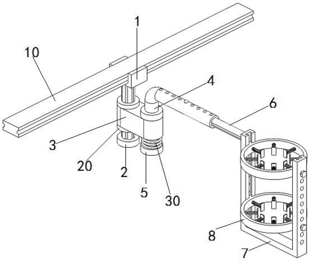
[0026] Such as figure 1 The shown fixed mechanism for a sputum suction bottle for clinical nursing includes a horizontally distributed installation beam 10, a positioning top seat 1 is installed on the installation beam 10, a lifting support 2 is installed vertically at the bottom of the positioning top seat 1, and the lifting support Two internal thread sleeves 20 are installed on the peripheral side, a rotating support 3 is installed between the two internal thread sleeves 20, a rotating adjusting seat 4 is installed at the outer end of the rotating support 3, and a limit base is installed at the bottom of the rotating adjusting seat 4 5. The first limit spring 30 is installed on the limit base 5, the outer end of the rotating adjusting seat 4 is connected with a telescopic connecting rod 6, the outer end of the telescopic connecting rod 6 is connected with a support frame 7, and the support frame 7 is distributed with two elastics. Limiting mechanism 8;
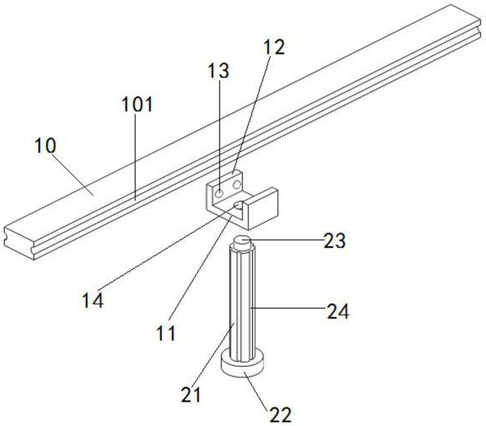
[0027] The mounting beam 10 is symmetrically provided with sliding limit transverse grooves 101 on both sides; the positioning top seat 1 includes a positioning bottom plate 11 and a sliding clamping plate 12 symmetrically arranged on both sides of the positioning bottom plate 11. The inner surface of the sliding clamping plate 12 is symmetrically provided with two A rolling ball 13 matched with the sliding limit horizontal groove 101, a fastening screw hole 14 is provided in the center of the positioning bottom plate 11; the lifting support 2 includes a lifting support screw 21 and a limit bottom plate 22 arranged at the bottom of the lifting support screw 21, The top of the lifting support screw 21 is provided with a fastening stud 23 that matches with the fastening screw hole 14, and the circumferential side of the lifting support screw 21 is uniformly distributed with a limited vertical slot 24;
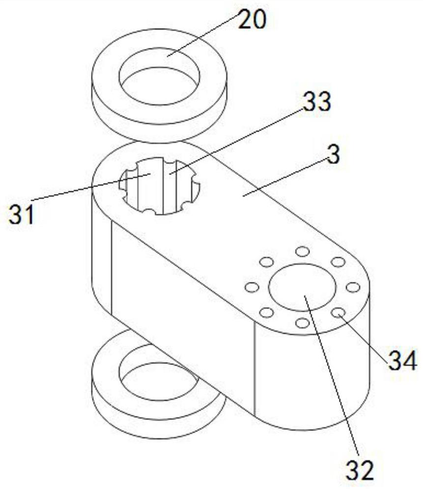
[0028] One end of the rotation support 3 is provided with a rotation limit hole 31 that matches with the lifting support screw 21, and the other end of the rotation support 3 is provided with a rotation adjustment hole 32. The inner side of the rotation limit hole 31 is evenly distributed with the limit vertical groove 24 The matching rotation limit protrusion 33, the outer side of the top end of the rotation adjustment hole 32 is evenly distributed with adjustment clamping holes 34, and the surface of the rotation support 3 is in close contact with the internal thread sleeve 20;
[0029] The rotating adjusting seat 4 includes a rotating pressing block 41 and a rotating connecting column 42 vertically arranged at the bottom of the rotating pressing block 41. A supporting column 43 is installed on the top of the rotating pressing block 41. A telescopic connecting tube 44 is connected to the top of the supporting column 43. The telescopic connecting tube Two telescopic limiting protrusions 45 are symmetrically provided on the inner side of 44. The top of the telescopic connecting pipe 44 is uniformly distributed with elastic limiting grooves 46 along the axial direction. The bottom edge of the rotating pressure block 41 is uniformly distributed with adjusting clamping holes 34. Adjusting the clamping protrusion 47, the bottom surface of the rotating connecting column 42 is provided with a fixed connection screw hole 48; the limit base 5 includes a limit stop 51, and the middle of the limit stop 51 is provided with a fixed connection that matches the fixed connection screw hole 48 Stud 52; a first limiting spring 30 is installed at the bottom end of the circumferential side of the rotating connecting column 42, and the two ends of the first limiting spring 30 are respectively connected to the limiting block 51 and the rotating support 3 in contact;
[0030] One end of the telescopic connecting rod 6 is provided with an elastic limiting protrusion 62 that matches with the elastic limiting slot 46, the other end of the telescopic connecting rod 6 is provided with an insertion slot 63, and the telescopic connecting rod 6 is symmetrically provided with the telescopic limiting The telescopic limit slot 61 matched with the protrusion 45; the support frame 7 includes a support bottom beam 71 and a support longitudinal beam 72 symmetrically arranged at both ends of the support bottom beam 71, and a guide adjustment slot 73 is vertically provided inside the support longitudinal beam 72, The outer side of the support longitudinal beam 72 is evenly distributed along the vertical direction with positioning screw holes 74 that communicate with the guide adjustment groove 73, and the top of one of the support longitudinal beams 72 is horizontally provided with an insertion strip 75 that matches the insertion groove 63;
[0031] The elastic limit mechanism 8 includes a limit ring 81 and a second limit spring 82 evenly distributed inside the limit ring 81. The inner end of the second limit spring 82 is connected to the limit stop plate 83. The inner surface of the limit ring 81 is along the circumference Spring mounting protrusions 811 that cooperate with the second limit spring 82 are uniformly distributed in the direction. The outer side of the limit ring 81 is symmetrically provided with guide adjustment protrusions 812 that cooperate with the guide adjustment groove 73. The guide adjustment protrusions 812 are connected with The positioning bolt 84 is matched with the positioning screw hole 74.
[0032] Among them, the guide adjustment groove 73 and the guide adjustment protrusion 812 are dovetail fit, the insertion groove 63 and the insertion strip 75 are interference fit, and the second limit spring 82 and the limit abutment plate 83 are welded Connected.
[0033] In specific use, first fix the mounting beam 10 to the edge of the bed bottom by bolts, and then install the above structures in sequence. According to actual use requirements, freely adjust the position of the positioning top seat 1 and fix it by tightening the top of the lifting support 2. , The rotating support 3 can be lifted and lowered freely and clamped and fixed by rotating and adjusting the two inner threaded sleeves 20, and the rotating adjusting seat 4 can be lifted up for free rotation and adjustment, and finally fixed and limited by adjusting the clamping protrusion 47. Adjust the telescopic connecting rod 6 for telescopic adjustment. By adjusting the relative positions of the two elastic limit mechanisms 8 up and down, it can be applied to the stable installation and fixation of sputum suction bottles of different sizes and heights; the second limit spring 82 and the limit abutment plate 83 The setting can quickly form a stable clamping of the sputum suction bottle to avoid shaking.
[0034] In the description of this specification, the description with reference to the terms "one embodiment", "example", "specific example", etc. means that the specific feature, structure, material or characteristic described in combination with the embodiment or example is included in at least the present invention. In one embodiment or example. In this specification, the schematic representation of the above-mentioned terms does not necessarily refer to the same embodiment or example. Moreover, the described specific features, structures, materials or characteristics may be combined in any one or more embodiments or examples in a suitable manner.
[0035] The basic principles, main features and advantages of the present invention have been shown and described above. Those skilled in the industry should understand that the present invention is not limited by the foregoing embodiments. The foregoing embodiments and descriptions only illustrate the principles of the present invention. Without departing from the spirit and scope of the present invention, the present invention will have Various changes and improvements, these changes and improvements all fall within the scope of the claimed invention.