Electric device for removing heavy metal in soil

A heavy metal and soil technology, applied in the restoration of polluted soil and other directions, can solve the problems such as the difficulty of adjusting the anode strong acid electrode solution in time, the difficulty of removing heavy metal ions to meet the actual needs, and the rainwater interfering with the treatment process.

Active Publication Date: 2020-10-13
浙江省有色金属地质勘查局 +1
View PDF10 Cites 0 Cited by
  • Summary
  • Abstract
  • Description
  • Claims
  • Application Information

AI Technical Summary

Problems solved by technology

Due to the fact that the gas generated by the anode electrode is difficult to discharge, the strong acidic electrode solution of the anode is difficult to be adjusted to neutral in time, and the rainwater interferes with the treatment process and other practical problems, which greatly hinder the DC electric field in the field electric repair process. Normal work, resulting in the removal efficiency of heavy metal ions is difficult to meet the actual needs

Method used


Image

  • Electric device for removing heavy metal in soil
  • Electric device for removing heavy metal in soil
  • Electric device for removing heavy metal in soil

Examples


Embodiment 1

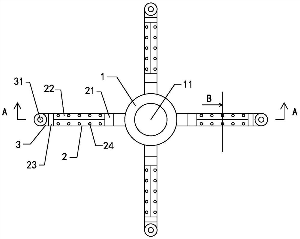
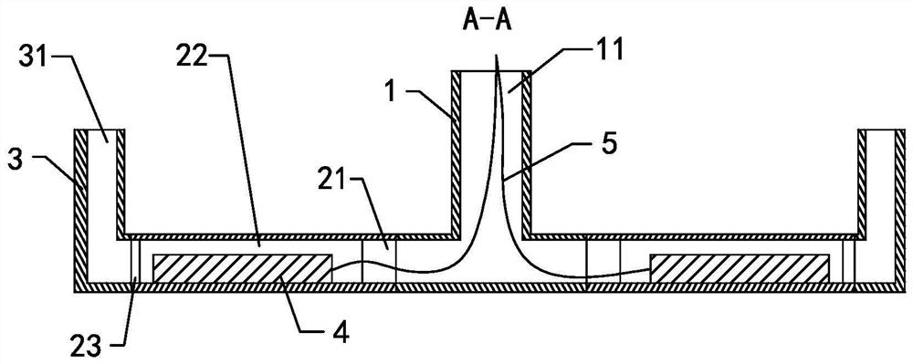
[0028] see Figure 1-3 , what this embodiment provides is a kind of electric soil heavy metal removal device, comprises power supply (not shown in the figure), cathode (not shown in the figure), anode rod 4, water inlet pipe 1, anode placement pipe and water outlet pipe 3.

[0029] The power supply is located above the soil, the anode rod 4 is located in the soil, the cathode is arranged on the soil surface, and the power supply, the anode rod 4 and the cathode are electrically connected in turn to form a loop. After the power is turned on, a DC electric field is formed between the anode rod 4 and the cathode, that is, between the anode rod 4 and the soil surface, and the heavy metal ions in the soil continue to migrate to the cathode.

[0030] The water inlet pipe 1, the anode placement pipe and the water outlet pipe 3 are connected in sequence. Water enters the water inlet pipe 1 from the water inlet 11 of the water inlet pipe 1, then flows through the anode placement pipe, ...

Embodiment 2

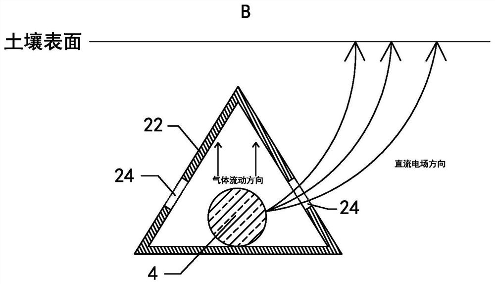
[0045] see Figure 4 The difference between this embodiment and Embodiment 1 is that the anode placement tube also includes a triangular prism 25 located below the placement section 22 , one side wall of the triangular prism 25 is fixed to the bottom outer wall of the placement section 22 . The bottom side edge of the triangular prism 25 can make the placement section 22 more easily pressed into the soil, and the solid triangular prism 25 after being pressed can make the center of gravity of the anode placement tube move down, so that the anode placement tube can be placed in the soil more easily. for stability. In this embodiment, the cross-sectional outline of the anode placement tube at the placement section 22 is quadrilateral, and further, the four vertices of the quadrilateral are located on the same circle, so that the cross section of the anode placement tube at the placement section 22 is closer to Round shape, thereby reducing the design length of the transition pip...

Embodiment 3

[0047] see Figure 5 The difference between this embodiment and Embodiment 1 is that the upper end of the main water inlet is provided with a water collecting funnel 12 that increases the area of ​​the water inlet 11, and the upper end of the outlet pipe 3 is provided with a ring cover 32 that reduces the area of ​​the water outlet 31. When it rains, the water collecting funnel 12 can increase the amount of rainwater collected at the water inlet 11. After the area of ​​the water outlet 31 shrinks, the amount of rainwater falling into the water outlet 31 is less than that at the water inlet 11, thereby ensuring the utilization of rainwater. In this case, prevent the liquid anolyte from flowing backward from the water outlet 31 to the water inlet 11.

[0048] In this embodiment, the outer wall of the outlet pipe 3 located above the soil is also provided with an annular buffer cover 37. The middle part of the buffer cover 37 is sunken downward, so that the entire buffer cover 37 ...


PUM


Abstract

The invention discloses an electric device for removing heavy metal in soil. The device comprises an anode bar, a water inlet pipe, an anode placing pipe and a water outlet pipe, wherein the water inlet pipe, the anode placing pipe and the water outlet pipe sequentially communicate with each other; the anode placing pipe is arranged horizontally and comprises a placing section; the cross section of the placing section is triangular; the anode bar is arranged in the placing section along the axial direction of the placing section; the anode bar is supported on the bottom wall of the placing section; liquid flowing into the placing section from the water inlet pipe flows through the bottom of the placing section; gas generated at the anode bar is gathered at the sharp top of the placing section; and anti-shielding water-permeable holes are formed in the bottom of the side wall of the placing section and used for preventing electrostatic shielding in the placing section and enabling the liquid in the placing section to make contact with soil.

Description

【Technical field】 [0001] The invention relates to an electrodynamic soil heavy metal removal device, which belongs to the field of soil heavy metal pollution control. 【Background technique】 [0002] Electric restoration treatment technology has the characteristics of small damage to soil structure, in-situ treatment, short treatment period and relatively low treatment price, and is suitable for the treatment of heavy metal pollution in cultivated land soil. The working principle of the electric device is to rely on the establishment of a direct current electric field to make the heavy metal ions in the soil continuously move to the cathode, and be adsorbed by the heavy metal capture material near the cathode, thereby removing the heavy metal ions in the soil. Due to the fact that the gas generated by the anode electrode is difficult to discharge, the strong acidic electrode solution of the anode is difficult to be adjusted to neutral in time, and the rainwater interferes wit...

Claims


Application Information

Patent Timeline
IPC IPC(8): B09C1/08
CPCB09C1/085
Inventor 周闻达
Owner 浙江省有色金属地质勘查局
Why Eureka
Try Eureka