
A Cutting Method of H-shaped Steel Based on Haunched End Plate

A technology of H-shaped steel and end plates, applied in the field of civil and architectural structures, can solve problems such as construction troubles, project waste, and inability to achieve systematization and serialization

Active Publication Date: 2021-09-14
SINOPEC SHANGHAI ENG +1
View PDF10 Cites 0 Cited by
  • Summary
  • Abstract
  • Description
  • Claims
  • Application Information

AI Technical Summary

Problems solved by technology

[0004] At present, the commonly used haunching joints in engineering include oblique haunching and straight haunching. There is no uniform design regulation for the specifications and sizes of such haunching joints. As a result, engineers are more arbitrary when designing haunching and cannot do so. Systematization and serialization also bring some troubles to the construction
Secondly, in previous projects, small sections of H-shaped steel left over from various steel structure frames can be seen everywhere on the construction site, which caused a lot of waste to the project

Method used


Image

  • A Cutting Method of H-shaped Steel Based on Haunched End Plate
  • A Cutting Method of H-shaped Steel Based on Haunched End Plate
  • A Cutting Method of H-shaped Steel Based on Haunched End Plate

Examples


Embodiment Construction

[0029] The present invention will be further described below in conjunction with the accompanying drawings and specific embodiments, but not as a limitation of the present invention.

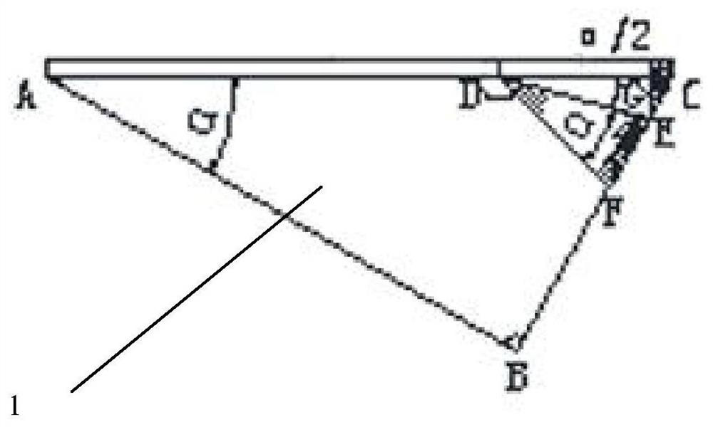
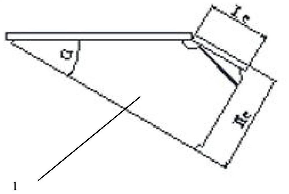
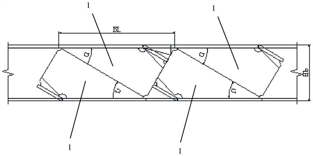
[0030] figure 1 It is the first schematic diagram of the H-shaped steel cutting method based on the haunched end plate of the present invention, figure 2 is the second schematic diagram of the H-shaped steel cutting method based on the haunched end plate of the present invention, image 3 It is a schematic drawing of the H-shaped steel cutting method based on the haunched end plate of the present invention, Figure 4 It is the installation diagram of the H-shaped steel cutting method based on the haunched end plate of the present invention, please refer to Figure 1 to Figure 4 As shown, the H-shaped steel cutting method based on the haunched end plate of a preferred embodiment is shown, including:

[0031] Step S1: Select H-shaped steel, the specification of H-shaped steel is the same as th...


PUM


Abstract

The invention discloses an H-shaped steel cutting method based on a haunched end plate, which includes: determining the starting point for cutting at the intersection A of the top of the web at the lower part of the upper flange of the steel beam, and cutting the web along the angle α direction of the flange of the H-shaped steel beam to The intersection point B of the bottom of the web and the lower flange of the H-shaped steel beam, then cut the web along the vertical direction AB to the top C of the web, and cut the upper flanges at A and C along the direction of the beam height to obtain a triangular web with flange ABC; Select point D between AC at the top of the H-shaped steel web, cut along the direction of α / 2 angle with the flange to edge E point, and then cut at point D to edge F along the DF line with α angle with DE. Cut the web and flange along the beam height direction EG at point E. At point D, the flange is cut along the beam height direction, and the flange DG is rotated clockwise by α, so that DE and the original DF are overlapped and welded, and the flange DG is perpendicular to the web edge BE. The cutting method of the present invention is simple and fast, can make full use of the remaining steel of the steel beam, improve the utilization rate of the steel, and effectively save the engineering cost.

Description

technical field [0001] The invention relates to the technical field of civil and architectural structures, in particular to an H-shaped steel cutting method based on a haunched end plate. Background technique [0002] In the past earthquakes, a large number of brittle fractures of the beam-column rigid connection joints occurred in the steel frame, indicating that the full-penetration butt weld between the beam flange and the column, and the high-strength butt weld between the beam web and the shear plate welded on the column The traditional rigid joint design connected by steel bolts did not meet the expected seismic design requirements. Most of the brittle fractures that occur in earthquakes occur in the lower part of the joints where little or no plastic deformation has developed, causing the lower flange of the beam to become the weak link in the fracture. Therefore, reducing the stress of the butt weld at the flange of the beam and forcing the formation of a plastic hi...

Claims


Application Information

Patent Timeline
Patent Type & Authority Patents(China)
IPC IPC(8): B23P15/00
CPCB23P15/00
Inventor 钱战坤俞海洪白桦傅晓红
Owner SINOPEC SHANGHAI ENG
Learn More