
Concrete prefabricating grouting sealing assembly inspection well

A prefabricated, concrete technology, applied in protection devices, water conservancy projects, artificial islands, etc., can solve the problems of easy corrosion and damage, difficult transportation, low service life, etc., to ensure stability and sealing, and reduce transportation volume and weight , Improve the effect of stability

Pending Publication Date: 2020-10-13
安徽华路畅安建材有限公司
View PDF0 Cites 1 Cited by
  • Summary
  • Abstract
  • Description
  • Claims
  • Application Information

AI Technical Summary

Problems solved by technology

[0003] The applicant found that the size of existing large-scale inspection wells is generally more than 2.5 meters. Due to the limited size and weight, it is difficult to transport as a whole, and the weight of an inspection well with an overall structure is also very large. Large-scale inspection wells are required for hoisting and installation. Lifting equipment is difficult to construct in places with limited site equipment, and the flexibility of use and installation is low. Therefore, large-scale inspection wells are generally split-assembled structures, but the existing concrete inspection wells with assembled structures are often only a few The simple splicing of concrete slabs has low stability of the connection, and it is easy to be squeezed, deformed and displaced after the external landfill, and it is difficult to keep the seal, and the joints are generally sealed with a sealing ring structure, which is easy to corrode and damage. lower lifespan

Method used


Image

  • Concrete prefabricating grouting sealing assembly inspection well
  • Concrete prefabricating grouting sealing assembly inspection well
  • Concrete prefabricating grouting sealing assembly inspection well

Examples


Embodiment Construction

[0032] In order to make the purpose, technical solutions and advantages of the present disclosure clearer, the present disclosure will be further described in detail below in conjunction with specific embodiments.

[0033] It should be noted that, unless otherwise defined, the technical terms or scientific terms used in one or more embodiments of the present specification shall have ordinary meanings understood by those skilled in the art to which the present disclosure belongs. "First", "second" and similar words used in one or more embodiments of the present specification do not indicate any order, quantity or importance, but are only used to distinguish different components. "Comprising" or "comprising" and similar words mean that the elements or items appearing before the word include the elements or items listed after the word and their equivalents, without excluding other elements or items. Words such as "connected" or "connected" are not limited to physical or mechanica...


PUM


Abstract

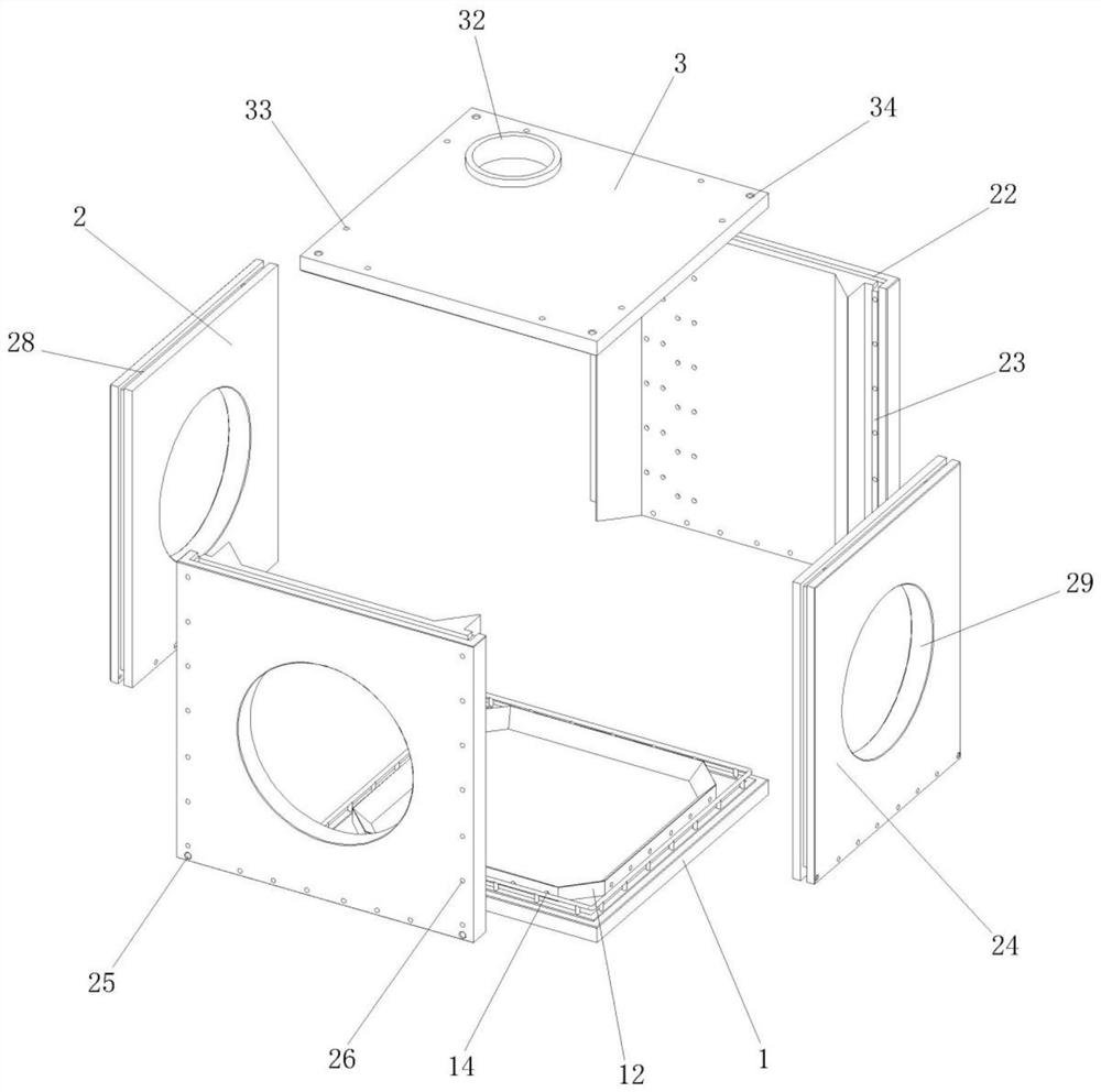
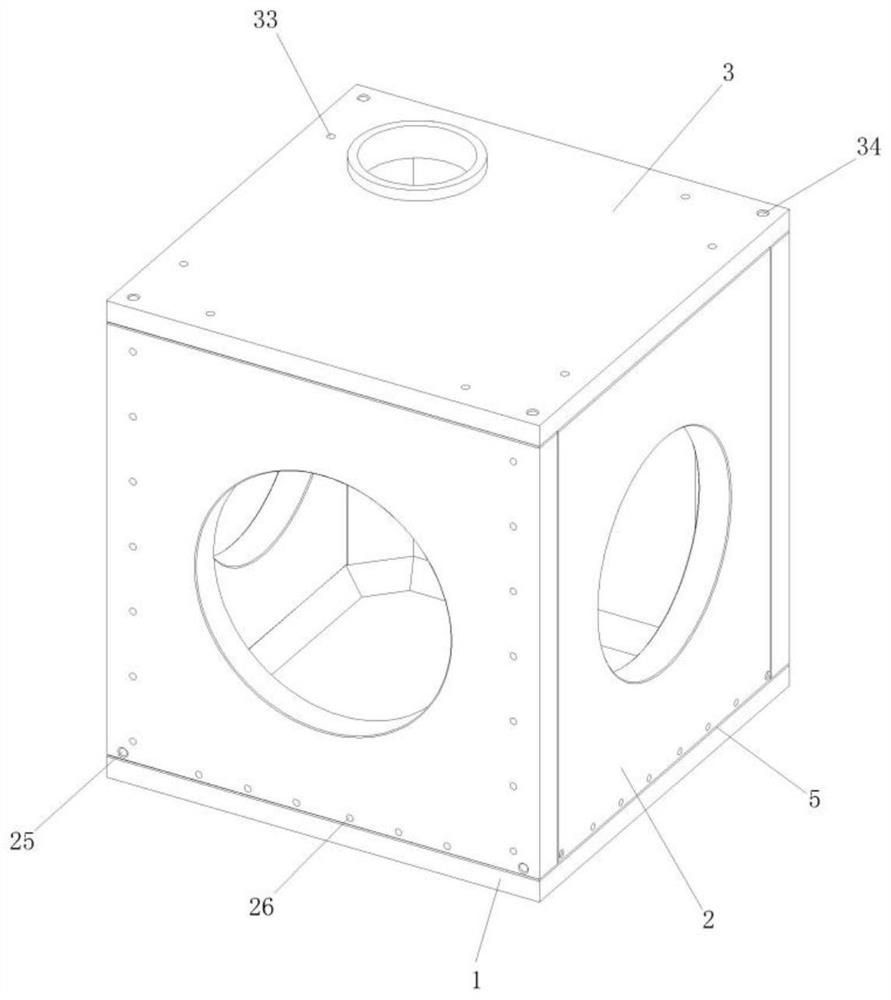
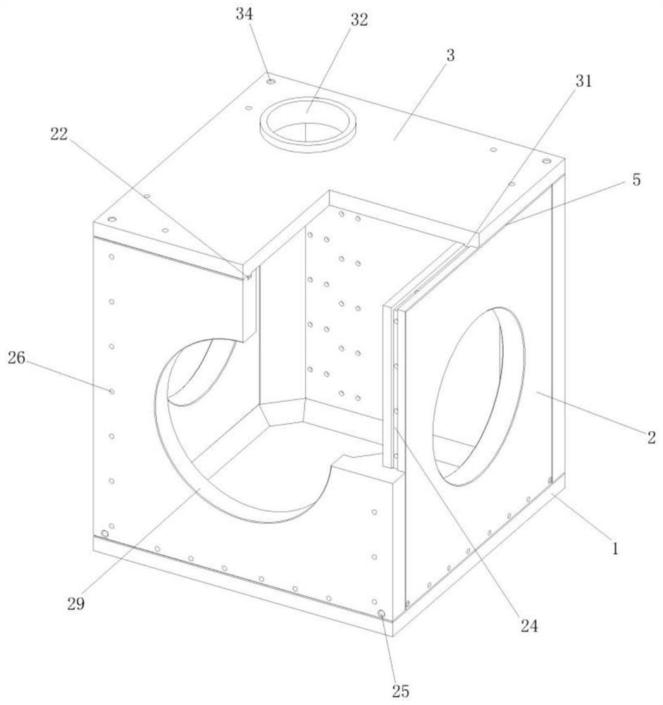
One or more embodiments of the invention provide a concrete prefabricating grouting sealing assembly inspection well which comprises a bottom plate, side vertical plates and a cover plate. The concrete prefabricating grouting sealing assembly inspection well is characterized in that bottom flanges are arranged on the periphery of the top of the bottom plate, and bottom inner chamfers are arrangedon the inner sides of the bottom flanges; the side vertical plates are located above the bottom plate, bottom grooves are formed in the lower ends of the side vertical plates, and grouting through holes are formed in the corners of the lower sides of the side vertical plates; and the cover plate is located above the side vertical plates. Due to the fact that the inspection well is overall dividedinto the bottom plate, the side vertical plates, the cover plate and multiple independent concrete prefabricated parts, the parts of the inspection well can be spliced and connected through arranged embedded grooves and connecting structures which are matched, meanwhile, clearances are reserved in the middles of the embedded concave-convex groove structures to form grouting channels, the parts canform net-shaped connecting structures through pouring of the grouting channels so as to be connected into a whole, and therefore the stability and sealing performance of the overall structure of theinspection well are ensured.

Description

technical field [0001] One or more embodiments of this specification relate to the technical field of concrete inspection wells, and in particular to a concrete prefabricated grouting sealed assembly type inspection well. Background technique [0002] The inspection well is set up for the maintenance of power supply, water supply, drainage, sewage discharge, communication, cable TV, gas pipe, street lamp line, etc. of urban underground infrastructure, and is convenient for installation. The changed places and the places at regular intervals on the straight pipe section are convenient for regular inspection of the ancillary structures. In order to maintain the stability of the structure, the large-scale inspection well is generally made of concrete. It needs to be made by pouring concrete with the corresponding formwork during production. The overall Larger in size and weight. [0003] The applicant found that the size of existing large-scale inspection wells is generally mo...

Claims


Application Information

Patent Timeline
IPC IPC(8): E02D29/12E02D29/14E02D31/02
CPCE02D29/12E02D29/14E02D29/1454E02D31/02
Inventor 韩子辉常志刚
Owner 安徽华路畅安建材有限公司
Learn More