Self-locking multi-cavity hydraulic oil cylinder and implementation method thereof

A hydraulic cylinder and fixed-type technology, applied in the direction of fluid pressure actuators, etc., can solve the problems of easy leakage and no self-locking structure, etc., and achieve the effects of flexible use, high precision and convenient use

Pending Publication Date: 2020-10-13
MAANSHAN YUHUA MACHINERY MFG
View PDF1 Cites 4 Cited by
  • Summary
  • Abstract
  • Description
  • Claims
  • Application Information

AI Technical Summary

Problems solved by technology

[0004] Although this application solves the problems in the background technology to a certain extent, there is no corresponding self-locking structure in this application, which is prone to leakage

Method used


Image

  • Self-locking multi-cavity hydraulic oil cylinder and implementation method thereof
  • Self-locking multi-cavity hydraulic oil cylinder and implementation method thereof
  • Self-locking multi-cavity hydraulic oil cylinder and implementation method thereof

Examples


Embodiment 1

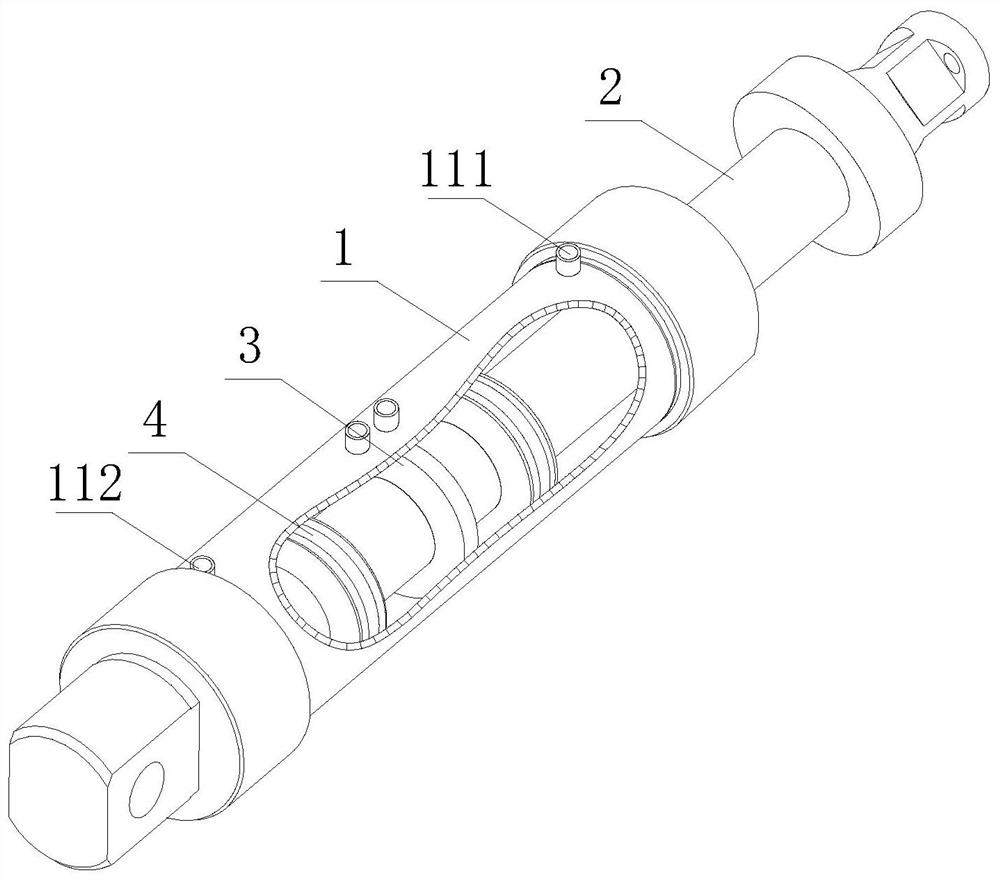
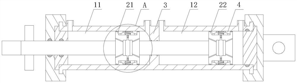
[0033] see Figure 1-Figure 2 , a self-locking multi-chamber hydraulic cylinder, including a cylinder body 1 and a piston rod 2, the two ends of the cylinder body 1 are respectively provided with a first cavity 11 and a second cavity 12, the first cavity 11 and the second cavity The two ends of the body 12 are respectively connected with a front oil port 111 and a rear oil port 112, the front oil port 111 and the rear oil port 112 are used for oil in and out, and a partition plate is arranged between the first cavity 11 and the second cavity 12 3. The partition plate 3 is used to separate the first cavity 11 and the second cavity 12. The piston rod 2 runs through the cylinder body 1, the piston rod 2 runs through the first cavity 11 and the second cavity 12, and the piston rod 2 The first piston 21 and the second piston 22 are respectively connected to the positions of the first cavity 11 and the second cavity 12, and the first piston 21 and the second piston 22 are connected ...

Embodiment approach

[0035] In order to better demonstrate the implementation process of the self-locking multi-chamber hydraulic cylinder, this embodiment now proposes an implementation method of the self-locking multi-chamber hydraulic cylinder, including the following steps:

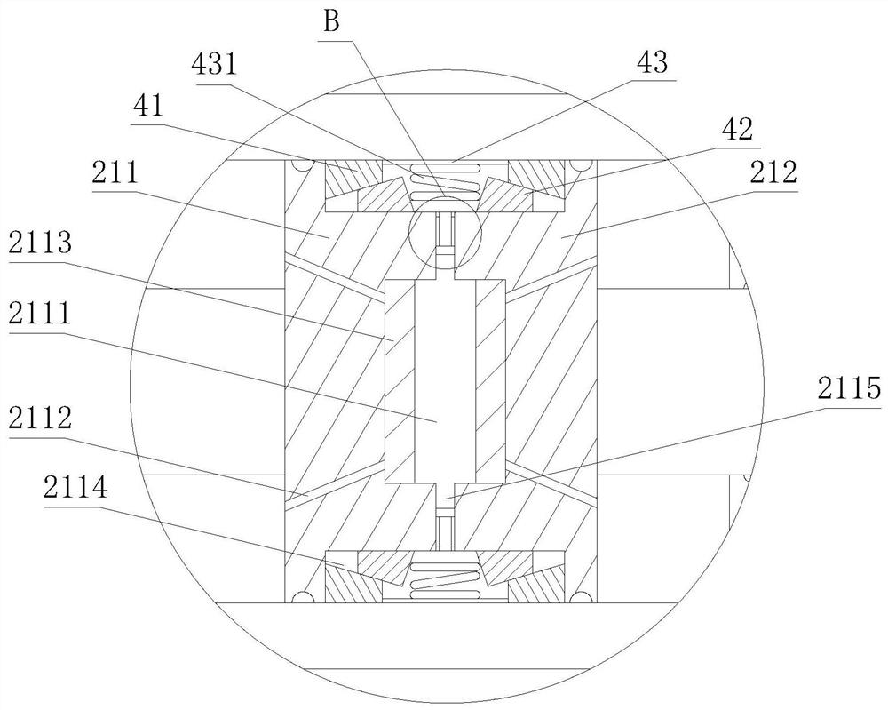
[0036] Step 1: The central groove 2111 is filled with internal oil body. When oil enters the front oil port 111 or the rear oil port 112 of the first cavity 11 and the second cavity 12 at the same time, the external oil body enters the first oil passage 2112 , and push the isolation plug 2113 to move the position, squeezing the inner oil body in the center groove 2111;

[0037] Step 2: The inner oil body flows under pressure, enters from the second oil passage 2115, pushes the moving position of the sealing block 4322, the guide post 4321 pushes the limit block 432 to move into the side wall groove 2114, and the locking spring 431 shrinks;

[0038] Step 3: The first locking ring 41 and the second locking ring 42 spread ap...

Embodiment 2

[0041] see Figure 7-Figure 9 , a self-locking multi-chamber hydraulic cylinder, comprising a cylinder body 1 and a piston rod 2, the two ends of the cylinder body 1 are respectively provided with a first cavity 11 and a second cavity 12, and the cylinder body 1 is penetrated with a piston rod 2 , the piston rod 2 runs through the first cavity 11 and the second cavity 12, and the piston rod 2 is placed in the position of the first cavity 11 and the second cavity 12 and connected with the first piston 21 and the second piston 22 respectively, A second locking device 5 is provided between the first cavity 11 and the second cavity 12, and a side wall groove 2114 is opened on the inner side of the second locking device 5, and the first locking ring 41 and the second locking ring 41 are installed in the side wall groove 2114. A locking ring 42, a fixed ring 43 is arranged between the first locking ring 41 and the second locking ring 42, and a locking spring 431 is equidistantly con...


PUM


Abstract

The invention discloses a self-locking multi-cavity hydraulic oil cylinder and an implementation method thereof. The self-locking multi-cavity hydraulic oil cylinder comprises an oil cylinder body anda piston rod. The two ends of the oil cylinder body are provided with a first cavity and a second cavity respectively. The piston rod penetrates through the oil cylinder body. The piston rod penetrates through the first cavity and the second cavity. The positions, in the first cavity and in the second cavity, of the piston rod are connected with a first piston and a second piston respectively. The first piston comprises a first half-piston and a second half-piston. According to the self-locking multi-cavity hydraulic oil cylinder and the implementation method thereof, the oil cylinder body isinternally provided with the first cavity and the second cavity, working chambers of the hydraulic cylinder are increased, different effective piston action areas can be provided, and different pressure grades can be generated; double locking can be achieved by installing first locking devices in the first piston and in the second piston, and the precision is high; and the first locking devices are arranged in the first cavity and in the second cavity, automatic unlocking is achieved when oil enters and goes out of the cavities, and the use is convenient.

Description

technical field [0001] The invention relates to the technical field of multi-chamber hydraulic cylinders, in particular to a self-locking multi-chamber hydraulic cylinder and an implementation method thereof. Background technique [0002] Oil cylinder self-locking is divided into oil circuit self-locking and mechanical self-locking. The self-locking of the oil circuit is to add a valve to maintain the pressure, so that the hydraulic oil of the oil cylinder does not return to the oil tank, and the oil cylinder is filled with a certain pressure oil. But this kind of pressure-maintaining self-locking is not very safe and reliable, if there is leakage, the cylinder rod will return slowly. The mechanical self-locking locks the cylinder rod through the mechanical structure to prevent the cylinder rod from moving when the oil cylinder fails. Functionally, mechanical self-locking can be further divided into mechanical self-locking that can only be self-locking in a specific positi...

Claims


Application Information

Patent Timeline
Patent Type & Authority Applications(China)
IPC IPC(8): F15B15/14F15B15/26
CPCF15B15/1447F15B15/26
Inventor 刘品华
Owner MAANSHAN YUHUA MACHINERY MFG
Why Eureka
Try Eureka