Infrared touch display
A touch display, infrared touch technology, applied in the direction of instrument, electrical digital data processing, data processing input/output process, etc., can solve the problem of EVA foam anti-vibration, waterproof, dustproof effect, complicated manual operation, Low efficiency and other problems, to avoid glass breakage, ensure life, and prolong life
- Summary
- Abstract
- Description
- Claims
- Application Information
AI Technical Summary
Problems solved by technology
Method used
Image
Examples
Embodiment 1
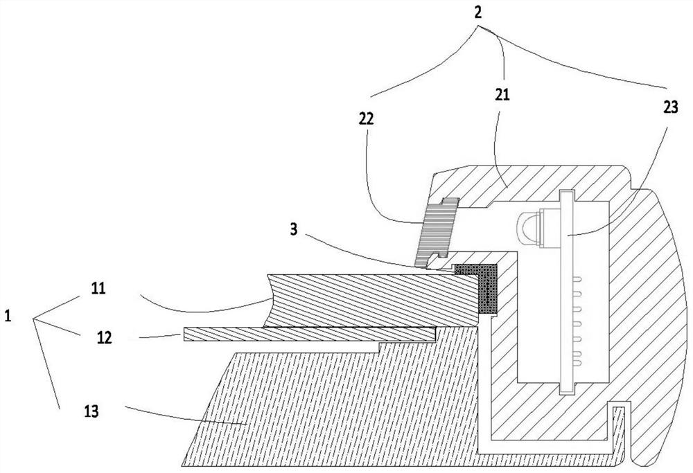
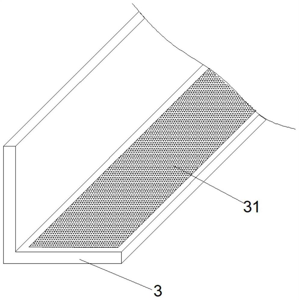
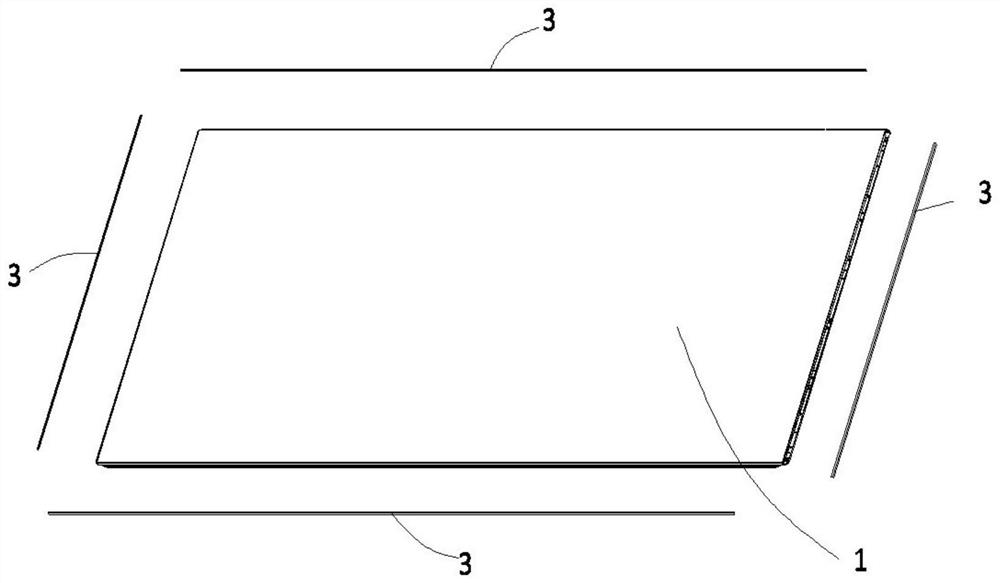
[0037] Please refer to figure 1 As shown, the infrared touch display according to the first embodiment of the present invention includes a display panel 1 and an infrared touch frame assembly 2 arranged along the edge of the display panel 1; A frame 21; a rubber pad 3 is provided between the contact surface of the frame 21 and the display panel 1. The contact surface in this embodiment includes the surface and side surfaces of the display panel 1 .
[0038] In the present invention, a rubber pad 3 is provided between the contact surface of the display panel 1 and the infrared touch frame assembly 2 to buffer the force generated by the collision between the display panel 1 and the frame 21 of the infrared touch frame assembly 2 during the assembly process, and further The possibility of broken display panel 1 due to collision is reduced; at the same time, the phenomenon of broken display panel 1 can also be avoided during transportation and use, and the shockproof effect of th...
Embodiment 2
[0054] Please refer to Figure 7 to Figure 13 As shown, the difference between the second embodiment of the present invention and the first embodiment is that: in this embodiment, a protrusion 32 is provided on the surface of the rubber pad 3 . In this embodiment, the protrusion 32 can increase the friction between the rubber pad 3 and the glass 11, and between the rubber pad 3 and the frame 21, so that the rubber pad 3 can be well fixed on the display panel under the pressure fit of the frame 21 1 and the frame 21, instead of fixing and bonding through the adhesive 31, the processing cost can be further reduced.
[0055] Please refer to Figure 7 As shown, in some embodiments of the present invention, the shape of the protrusion 32 can be a semicircle; please refer to Figure 8 As shown, the shape of the protrusion 32 can also be cylindrical; please refer to Figure 9 As shown, the shape of the protrusion 32 can also be conical; please refer to Figure 10 The shape of the...
PUM
 Abstract
Description
Claims
Application Information
 - R&D
- Intellectual Property
- Life Sciences
- Materials
- Tech Scout
- Unparalleled Data Quality
- Higher Quality Content
- 60% Fewer Hallucinations
Browse by: Latest US Patents, China's latest patents, Technical Efficacy Thesaurus, Application Domain, Technology Topic, Popular Technical Reports.
© 2025 PatSnap. All rights reserved.Legal|Privacy policy|Modern Slavery Act Transparency Statement|Sitemap|About US| Contact US: help@patsnap.com


