Packaging patch positioning method

A positioning method and mounting technology, which is applied in the direction of electrical components, semiconductor/solid-state device manufacturing, circuits, etc., can solve problems such as difficulty in locating the precise position of the bare chip 1, the influence of the rewiring process, and the inability to measure the mounting accuracy of the bare chip 1, etc. , to achieve the effect of meeting precision production requirements, ensuring success rate and product yield

Pending Publication Date: 2020-10-13
SIPLP MICROELECTRONICS CHONGQING CO LTD
View PDF6 Cites 1 Cited by
  • Summary
  • Abstract
  • Description
  • Claims
  • Application Information

AI Technical Summary

Problems solved by technology

[0003] like figure 1 As shown, when the die 1 is mounted on the carrier board 2, since there is no reference point on the carrier board 2, the position of the die 1 cannot be accurately positioned, and the mounting accuracy of the die 1 cannot be measured after mounting , so that in the subsequent rewiring process, it is difficult to locate the precise position of the die 1 in the carrier 2, which has a great impact on the rewiring process, and even makes it difficult to carry out the rewiring process

Method used


Image

  • Packaging patch positioning method
  • Packaging patch positioning method
  • Packaging patch positioning method

Examples


Embodiment Construction

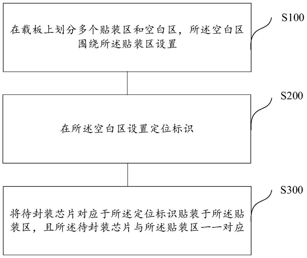
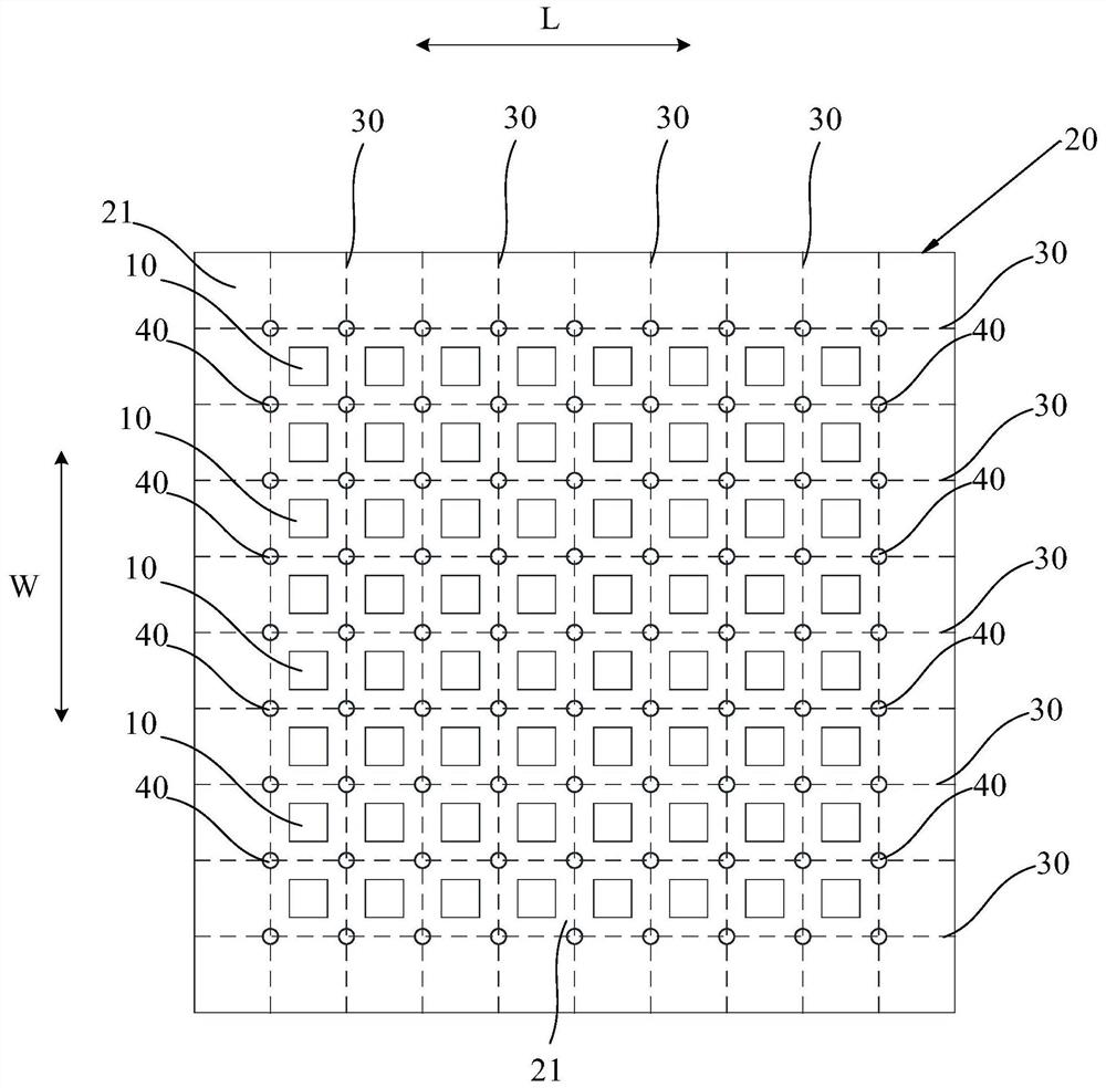
[0045] Reference will now be made in detail to the exemplary embodiments, examples of which are illustrated in the accompanying drawings. When the following description refers to the accompanying drawings, the same numerals in different drawings refer to the same or similar elements unless otherwise indicated. The implementations described in the following exemplary embodiments do not represent all implementations consistent with this application. Rather, they are merely examples of apparatuses and methods consistent with aspects of the present application as recited in the appended claims.

[0046] The terminology used in this application is for the purpose of describing particular embodiments only, and is not intended to limit the application. Unless otherwise defined, the technical terms or scientific terms used in the present application shall have the common meanings understood by those skilled in the art to which the present invention belongs. Words such as "one" or "o...


PUM


Abstract

The invention provides a packaging paster positioning method, and the method comprises the steps: dividing a carrier plate into a plurality of mounting regions and blank regions, and the blank regionsbeing arranged around the mounting regions; setting a positioning identifier in the blank area; and mounting chips to be packaged on the mounting areas in a manner of corresponding to the positioningidentifiers, wherein the chips to be packaged are in one-to-one correspondence with the mounting areas. According to the invention, the positioning identifier is arranged in the blank area of the carrier plate, the accurate position of the to-be-packaged patch on the carrier plate is positioned through the positioning identifier, the chip mounting precision in the chip mounting process can be ensured, and the chip mounting precision can be detected according to the position of the positioning identifier, so that the mounting position of the to-be-packaged chip can be adjusted in real time, and meanwhile, the precision production requirements of subsequent processes can be met, thereby ensuring the success rate of later packaging and the yield of products.

Description

technical field [0001] The present application relates to the technical field of semiconductors, and in particular to a packaging patch positioning method. Background technique [0002] Common semiconductor packaging technology, such as chip packaging technology, mainly includes the following process: first, a layer of film is pasted on the carrier, and the film can be degraded by heating or laser. The front side of the bare chip is bonded to the carrier board, heat-pressed and molded, then the carrier board is peeled off, and then a rewiring process is performed on the front side of the bare chip to form a rewiring structure and packaged. [0003] Such as figure 1 As shown, when the die 1 is mounted on the carrier board 2, since there is no reference point on the carrier board 2, the position of the die 1 cannot be accurately positioned, and the mounting accuracy of the die 1 cannot be measured after mounting , so that in the subsequent rewiring process, it is difficult t...

Claims


Application Information

Patent Timeline
Patent Type & Authority Applications(China)
IPC IPC(8): H01L21/67H01L21/68
CPCH01L21/68H01L21/67259H01L21/67294
Inventor 霍炎陈莉
Owner SIPLP MICROELECTRONICS CHONGQING CO LTD
Why Eureka
Try Eureka