PCB surface mounting equipment

A surface mount and PCB board technology, which is applied to the assembly of printed circuits with electrical components, electrical components, and printed circuit manufacturing. It can solve problems such as low work efficiency and large product quality defects, and achieve the effect of ensuring mounting accuracy.

Pending Publication Date: 2022-01-11
康正明
View PDF0 Cites 0 Cited by
  • Summary
  • Abstract
  • Description
  • Claims
  • Application Information

AI Technical Summary

Problems solved by technology

[0003] With the rapid growth of human social needs, people's rapid delivery capability and quality requirements for products have become very important. The defects of traditional manual placement technology have become more and more prominent, with large product quality defects and low work efficiency. , for this reason, the present invention proposes a kind of PCB surface mount equipment that can solve the above problems

Method used


Image

  • PCB surface mounting equipment
  • PCB surface mounting equipment
  • PCB surface mounting equipment

Examples


Embodiment 1

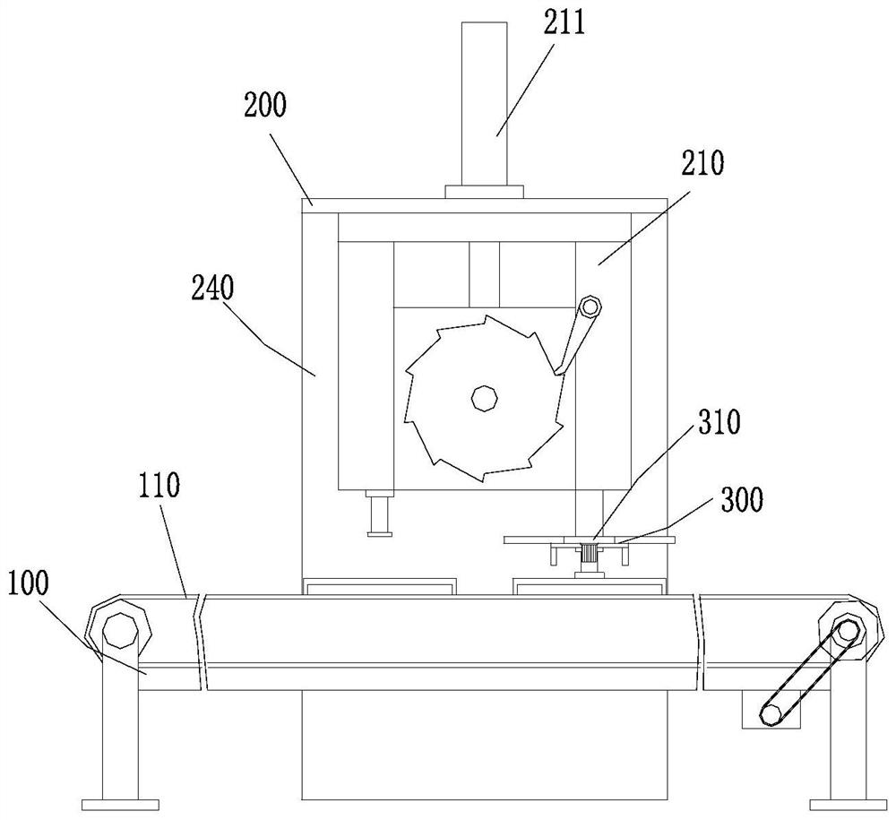
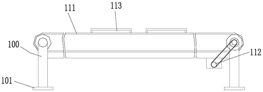
[0039] The present invention provides a technical solution: a PCB surface mount equipment, including a workbench 100, a conveying mechanism 110 is arranged on the workbench 100, and the conveying mechanism 110 is used to convey the PCB board. The conveyor belt 111 and the first servo motor 112 arranged at the lower end of the workbench 100, the first servo motor 112 is used to drive the conveyor belt 111 to move at intervals, the conveyor belt 111 is provided with several groups of placement grooves 113 at intervals, and the placement grooves 113 For positioning and placing PCB boards;

[0040] Fixed frame 200, fixed frame 200 is arranged on the middle part of the upper end of workbench 100, and mounting mechanism 210 is installed on the fixed frame 200, and mounting mechanism 210 comprises first movable arm 216, second movable arm 215 and driving assembly, and driving assembly is used for Drive the first movable arm 216 and the second movable arm 215 to lift respectively. The...

Embodiment 2

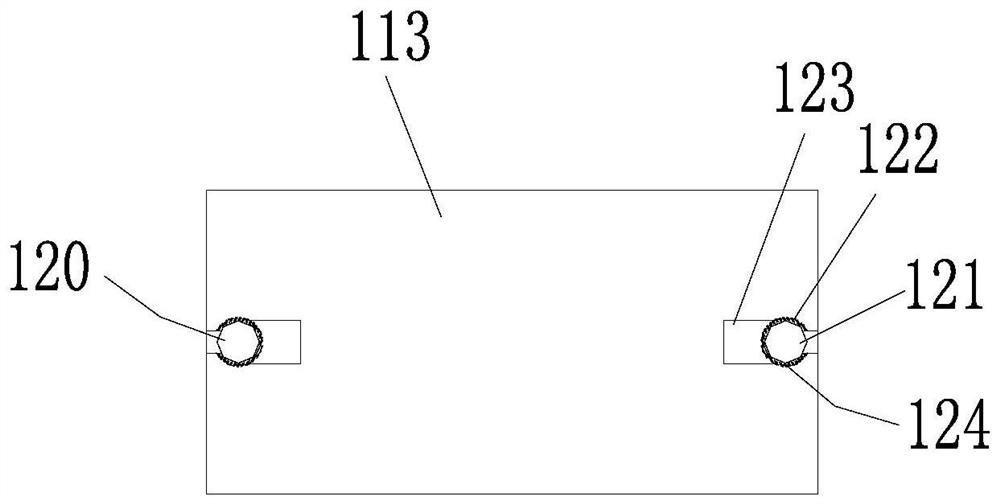
[0044] On the basis of Embodiment 1, the lower end of the workbench 100 is provided with supporting legs, and the supporting legs are affixed to the ground through the connecting plate 101; Clamping mechanism 120. The clamping mechanism 120 includes support rods 121 arranged on both sides of the placement groove 113. A movable sleeve 122 is sleeved on the support rod 121. One side of the movable sleeve 122 is connected with an abutment plate 123. The support rod 121 is wound with Compression spring 124, compression spring 124 is connected with movable sleeve 122; Adsorption mechanism 230 comprises the suction nozzle 232 that is arranged on the lower end of first movable arm 216, and suction nozzle 232 is equipped with driving source 231, can control suction nozzle 232 to carry out suction action and drop actions.

[0045] Specifically, the workbench 100 is fixedly connected to the ground, and when working, the overall state is kept stable, and the PCB board in the placement gr...


PUM


Abstract

The invention discloses PCB surface mounting equipment, and the equipment comprises a workbench, a conveying mechanism which is arranged on the workbench and used for conveying a PCB and a fixing frame arranged in the middle of the upper end of the workbench; a mounting mechanism is mounted on the fixing frame, and the mounting mechanism comprises a first movable arm, a second movable arm and a driving assembly. An adsorption mechanism is arranged at the lower end of one movable arm, and a pressing plate is arranged at the lower end of the other movable arm; The equipment also comprises a supporting frame which is arranged below the fixing frame, wherein a feeding mechanism is arranged on the supporting frame, and the feeding mechanism comprises a rotating disc rotationally arranged at the upper end of the supporting frame and a second servo motor arranged below the supporting frame. According to the invention, full-automatic mounting operation is carried out on the PCB, secondary pressing is carried out on the mounted chip, the mounting efficiency is high, the quality is high, and the chip is effectively prevented from loosening on the PCB.

Description

technical field [0001] The invention relates to the field of surface mount technology, in particular to a PCB surface mount device. Background technique [0002] The electronic information product manufacturing industry is growing at a rate of more than 20% every year; surface mount or surface mount technology is a method of mounting non-pin or short lead surface mount components on printed circuit boards (Printed Circuit Board, PCB) surface or other substrate surface technology. [0003] With the rapid growth of human social needs, people's rapid delivery capability and quality requirements for products have become very important. The defects of traditional manual placement technology have become more and more prominent, with large product quality defects and low work efficiency. Therefore, the present invention proposes a PCB surface mount device capable of solving the above problems. Contents of the invention [0004] The object of the present invention is to provide ...

Claims


Application Information

Patent Timeline
Patent Type & Authority Applications(China)
IPC IPC(8): H05K3/30H05K13/04H05K13/00
CPCH05K3/303H05K13/0417H05K13/0406H05K13/0409H05K13/0069H05K13/0015
Inventor 康正明
Owner 康正明
Why Eureka
Try Eureka