Display panel and display device

A display panel and display area technology, applied in the direction of semiconductor devices, electrical components, circuits, etc.

Active Publication Date: 2020-10-13
WUHAN TIANMA MICRO ELECTRONICS CO LTD
View PDF18 Cites 22 Cited by
  • Summary
  • Abstract
  • Description
  • Claims
  • Application Information

AI Technical Summary

Problems solved by technology

[0004] Embodiments of the present invention provide a display panel and a display device to improve the problem of color shift in four directions, improve the display effect of the OLED display panel, and improve the user's viewing experience

Method used


Image

  • Display panel and display device
  • Display panel and display device
  • Display panel and display device

Examples


Embodiment Construction

[0033] The present invention will be further described in detail below with reference to the drawings and embodiments. It can be understood that the specific embodiments described here are only used to explain the present invention, but not to limit the present invention. In addition, it should be noted that, for ease of description, the drawings only show part of the structure related to the present invention, but not all of the structure.
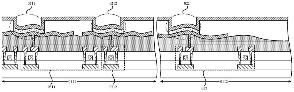
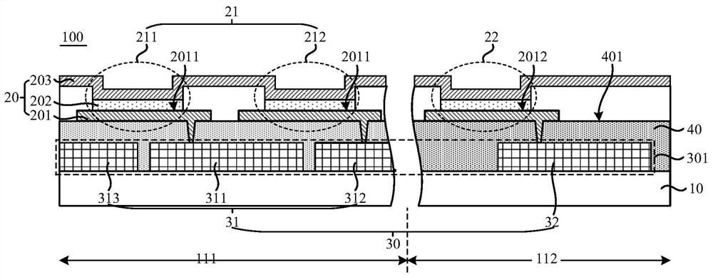
[0034] The display area of ​​the display panel is provided with a plurality of sub-pixels, and each sub-pixel includes a light-emitting element and a pixel driving circuit. Generally, the light-emitting element is located on the side of the pixel driving circuit away from the base substrate, and the light-emitting element is electrically connected with the pixel driving circuit, so that the pixel driving circuit can drive the light-emitting element to display and emit light. The pixel drive circuit includes thin film transistors, capacitors...


PUM


Abstract

The embodiment of the invention provides a display panel and a display device. A display area of the display panel comprises a high-transmittance area and a first display area surrounding the high-transmittance area. A pixel circuit layer and a plurality of light-emitting elements are sequentially arranged on one side of a substrate of the display panel. The pixel circuit layer comprises a plurality of pixel driving circuits; each of the light-emitting elements comprises a first electrode, a second electrode and a light-emitting layer located between the first electrode and the second electrode, and each first electrode is located on the side, close to the substrate, of the second electrode. The first electrodes of the light-emitting elements are electrically connected with the pixel driving circuits in a one-to-one correspondence manner, the density of the first light-emitting elements in the high-transmittance area is smaller than that of the second light-emitting elements in the first display area; the difference between the flatness of the surfaces of the sides, away from the substrate, of the first electrodes of the first light-emitting elements and the flatness of the surfaceof the sides, away from the substrate, of the first electrodes of the second light-emitting elements is within a first preset range. The embodiment of the invention can improve the color cast problemand improve the display effect.

Description

Technical field [0001] The present invention relates to the field of display technology, and in particular to a display panel and a display device. Background technique [0002] With the development of display technology, display devices have gradually progressed from a narrow frame to a borderless visual effect to increase the screen-to-body ratio of the display device. The optical sensor module of the high screen-to-body ratio display device, such as a camera, an infrared sensor Etc., will be set in its display area. At present, in order to make the area where the optical sensor module is installed have a higher light transmittance, the pixel density of the area where the optical sensor module is installed is usually reduced. [0003] When the display panel of the display device is an Organic Light-Emitting Diode (OLED) display panel, the OLED element of the OLED display panel is a current-driven element, and a corresponding pixel drive circuit needs to be provided to provide dr...

Claims


Application Information

Patent Timeline
Patent Type & Authority Applications(China)
IPC IPC(8): H01L27/32
CPCH10K59/60H10K59/122H10K59/123H10K59/1213H10K59/1315
Inventor 罗雅琴叶亮胡峻霖
Owner WUHAN TIANMA MICRO ELECTRONICS CO LTD
Why Eureka
Try Eureka