Rotor core of segmented skewed-pole motor and permanent magnet synchronous motor
A rotor core and oblique pole technology, applied in the direction of magnetic circuits, electric components, electrical components, etc., can solve the problem that the comprehensive vibration and noise reduction effect is not optimal, so as to achieve a good comprehensive vibration and noise reduction effect and suppress vibration Effects of noise, reduction of torque ripple and radial electromagnetic force
- Summary
- Abstract
- Description
- Claims
- Application Information
AI Technical Summary
Problems solved by technology
Method used
Image

Examples
Embodiment 1
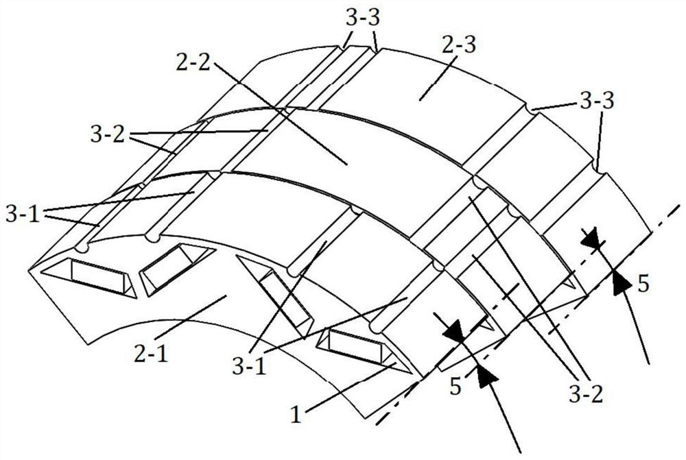
[0039] One embodiment of the present invention discloses a rotor core of a segmented oblique pole motor, such as figure 1 As shown, the rotor core includes a plurality of rotor core segments that are mutually staggered by a preset angle of 5, and the rotor core segments are formed by stacking rotor punches, and the rotor punches are stamped and formed; in the rotor core When the segments are assembled, the preset angle 5 is staggered between the rotor core segments, thereby reducing the cogging effect caused by the slots on the stator.
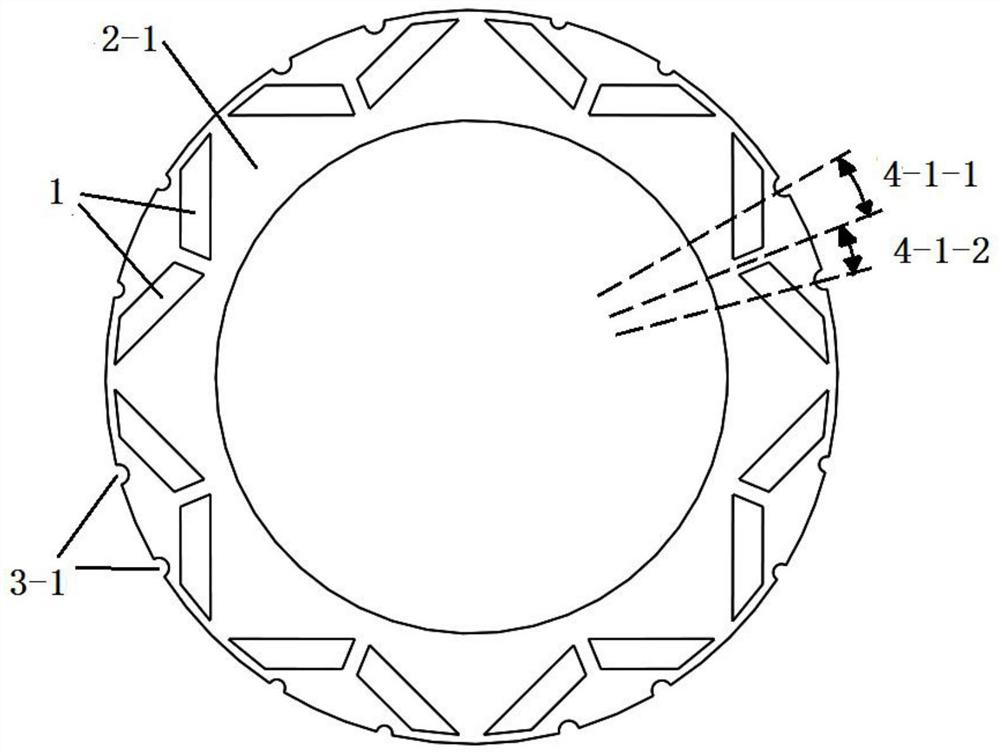
[0040] Each of the rotor core segments is provided with a magnetic steel slot 1 along the circumferential direction, and a magnetic steel slot can be arranged in the magnetic steel slot 1; the number of magnetic steel slots 1 is an even number, and two adjacent magnetic steel slots 1 are arranged symmetrically .
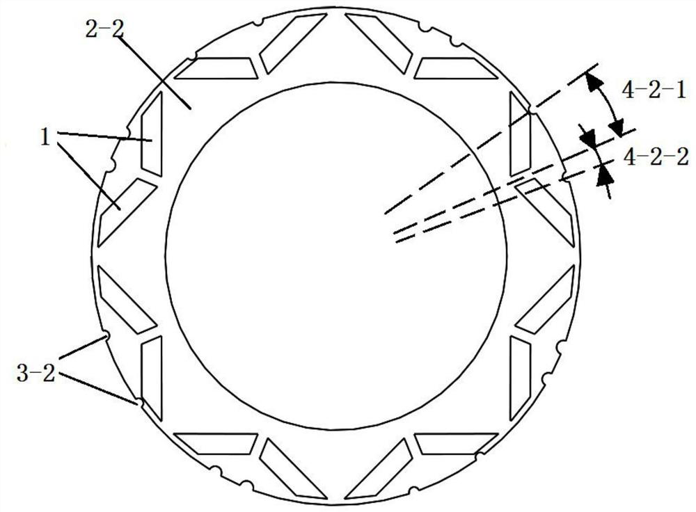
[0041] The outer circular surface of each rotor core segment is provided with several axially penetrating auxiliary grooves, and t...
Embodiment 2
[0064] An embodiment of the present invention discloses a permanent magnet synchronous motor. The permanent magnet synchronous motor includes a stator and a rotor, and the rotor is provided with the above-mentioned rotor core. The permanent magnet synchronous motor in this embodiment has low vibration noise and high NVH (Noise, Vibration, Harshness) quality.
[0065] To sum up, the present invention discloses a rotor core of a segmented oblique pole motor and a permanent magnet synchronous motor, including a plurality of rotor core segments staggered from each other by a preset angle, and the rotor core segments are laminated by rotor punching sheets; Each rotor core section is provided with a magnetic steel groove along the circumferential direction, and a magnetic steel can be arranged in the magnetic steel groove; there are several axially penetrating auxiliary grooves on the outer surface of each rotor core section, and each rotor iron The positions and / or cross-sectional ...
PUM
 Abstract
Description
Claims
Application Information
 - R&D
- Intellectual Property
- Life Sciences
- Materials
- Tech Scout
- Unparalleled Data Quality
- Higher Quality Content
- 60% Fewer Hallucinations
Browse by: Latest US Patents, China's latest patents, Technical Efficacy Thesaurus, Application Domain, Technology Topic, Popular Technical Reports.
© 2025 PatSnap. All rights reserved.Legal|Privacy policy|Modern Slavery Act Transparency Statement|Sitemap|About US| Contact US: help@patsnap.com