
Separation vibrating screen for drilling fluid

A vibrating screen and drilling fluid technology, which is applied in filtration and separation, separation methods, dispersed particle separation, etc., can solve the problems of complex equipment, high mud viscosity, inability to separate drilling fluid and cuttings, etc., and achieve the effect of saving energy.

Inactive Publication Date: 2020-10-16
阳忠海
View PDF4 Cites 2 Cited by
  • Summary
  • Abstract
  • Description
  • Claims
  • Application Information

AI Technical Summary

Problems solved by technology

[0003] In the process of separating the drilling fluid, the drilling fluid shale shaker works under open or semi-open conditions, the upper and lower parts of the screen surface are at atmospheric pressure, and the drilling fluid is separated by the vibration of the sieve plate. If the vibration amplitude is too small, the drilling fluid and cuttings cannot be separated, and if the vibration amplitude is too large, it is easy to cause the drilling fluid to splash, so now there is a negative pressure vibrating screen, so that the vibration amplitude is too small, and the drilling fluid can be quickly However, during the use of the currently used vibrating screen, negative pressure equipment is directly used to provide negative pressure for the bottom of the vibrating screen, and a special gas-liquid separation device needs to be installed in the process of separating the drilling fluid from the negative pressure air , it is also necessary to provide power for the gas-liquid separation device, and the equipment is relatively complicated
[0004] After the mud separation of the drilling fluid is completed, it is inevitable that a large amount of small cuttings will be mixed inside the mud, which will also affect the use of later drilling equipment, and the long-term circulation of the drilling fluid will also make the viscosity of the mud more and more The bigger it is, the less effective the drilling fluid will be on the drilling equipment

Method used


Image

  • Separation vibrating screen for drilling fluid
  • Separation vibrating screen for drilling fluid
  • Separation vibrating screen for drilling fluid

Examples


Embodiment Construction

[0023] The following will clearly and completely describe the technical solutions in the embodiments of the present invention with reference to the accompanying drawings in the embodiments of the present invention. Obviously, the described embodiments are only some, not all, embodiments of the present invention. Based on the embodiments of the present invention, all other embodiments obtained by persons of ordinary skill in the art without making creative efforts belong to the protection scope of the present invention.

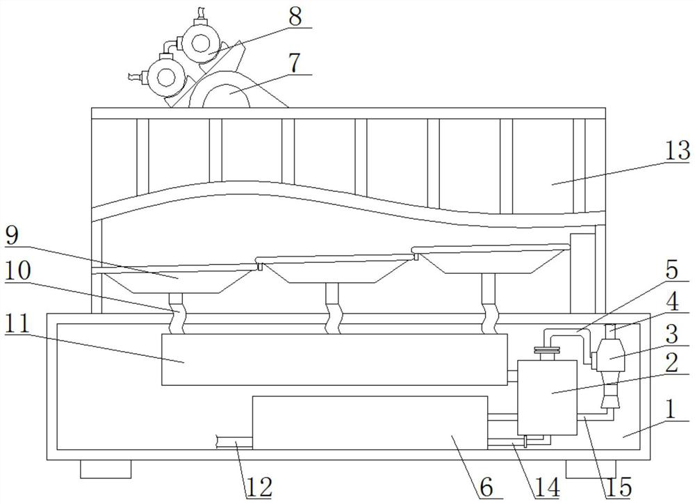
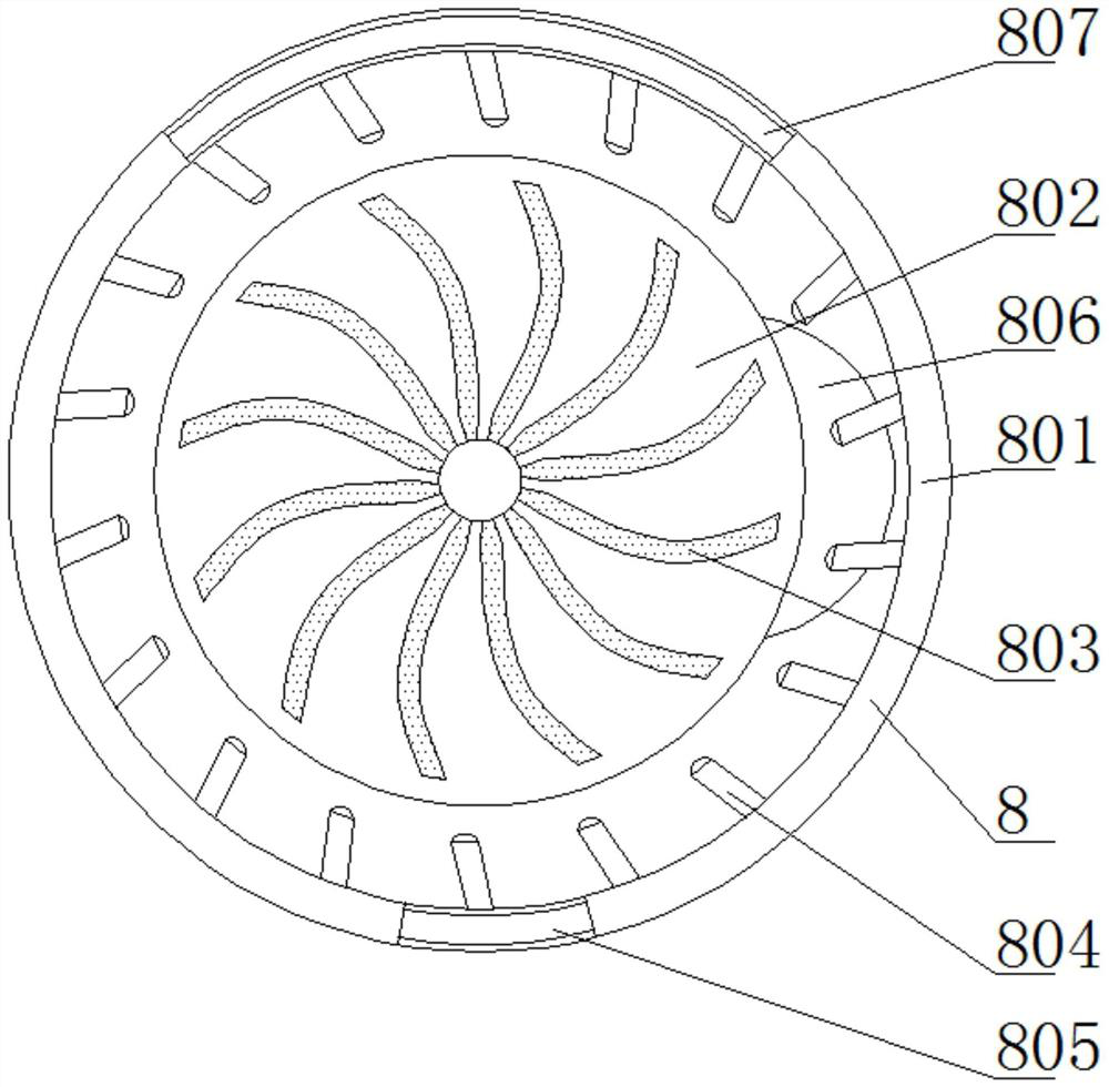
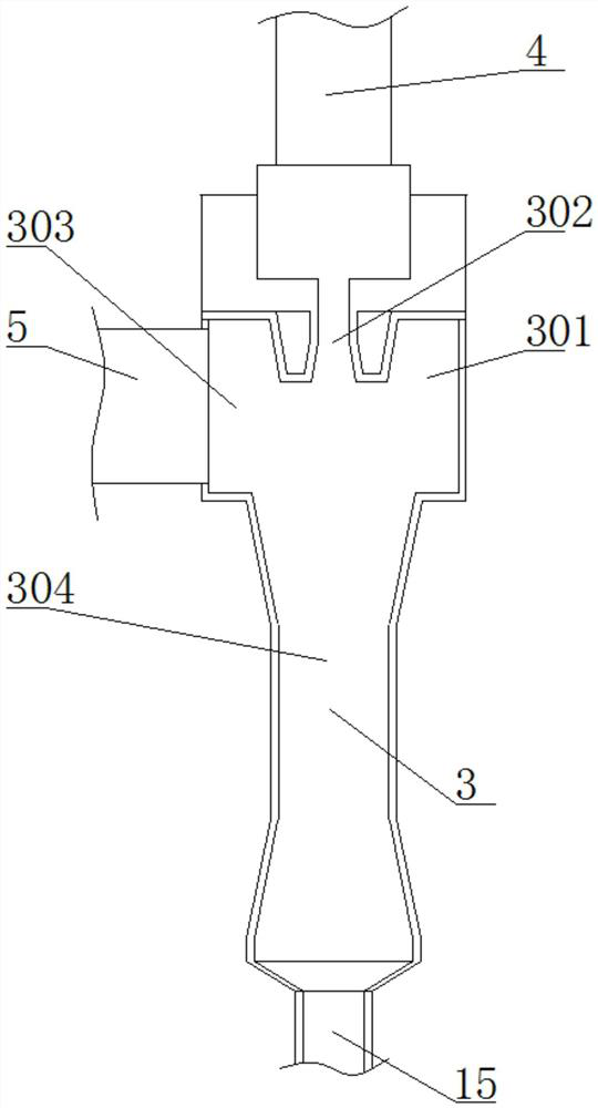
[0024] see Figure 1-5 , a separation vibrating screen for drilling fluid, comprising a base 1, a screen frame 13 is movably installed on the top of the base 1, a placement seat 7 is fixedly installed on the top of the screen frame 13, and a vibration excitation device 8 is fixedly installed on the top of the placement seat 7, A screen device 9 is fixedly installed on the front of the inner cavity of the screen frame 13, and a connecting hose 10 is fixedly con...


PUM


Abstract

The invention relates to the technical field of drilling fluid separation equipment, and discloses a separation vibrating screen for drilling fluid. The separation vibrating screen comprises a base, ascreen frame is movably mounted at the top of the base, a placement plate is fixedly mounted at the top of the screen frame, a vibration excitation device is fixedly mounted at the top of the placement base, a screen device is fixedly mounted on the front surface of an inner cavity of the screen frame, a communicating hose fixedly communicates with the bottom of the screen device, and a negativepressure chamber is fixedly mounted on the front surface of the inner cavity of the base. According to the separation vibrating screen for the drilling fluid, a spiral pneumatic blade, an injector head and an eccentric block are arranged in the vibration excitation device and are matched with one another, external compressed air enters the outer side cavity through the air inlet, and the sprayinghead sprays the compressed air to the outer surface of the spiral pneumatic blade so that the device provides a vibrating source for the vibrating screen through the compressed air, a special vibrating motor does not need to be arranged, and energy is saved.

Description

technical field [0001] The invention relates to the technical field of drilling fluid separation equipment, in particular to a drilling fluid separation vibrating screen. Background technique [0002] Drilling fluid is a general term for various circulating fluids that meet the needs of drilling work with its various functions during the drilling process. Drilling fluid is the blood of drilling, also known as drilling flushing fluid. Drilling fluid can be divided into water, mud, and inorganic Clay phase washing fluid, emulsion, foam and compressed air, etc. [0003] In the process of separating the drilling fluid, the drilling fluid shale shaker works under open or semi-open conditions, the upper and lower parts of the screen surface are at atmospheric pressure, and the drilling fluid is separated by the vibration of the sieve plate. If the vibration amplitude is too small, the drilling fluid and cuttings cannot be separated, and if the vibration amplitude is too large, it...

Claims


Application Information

Patent Timeline
IPC IPC(8): B01D33/03B01D33/80B01D36/00B01D45/16C02F11/121C02F103/10
CPCB01D33/03B01D33/801B01D36/001B01D45/16C02F11/121C02F2103/10
Inventor 阳忠海
Owner 阳忠海
Learn More