A planetary roller screw

A technology of planetary rollers and rollers, applied in the direction of transmission, belt/chain/gear, mechanical equipment, etc., can solve the problems of planetary roller-screw transmission ratio change, slip, inability to realize fixed transmission ratio transmission, etc. To achieve the effect of improving stability and accuracy, and improving accuracy

Active Publication Date: 2022-04-08
BEIJING RES INST OF PRECISE MECHATRONICS CONTROLS
View PDF23 Cites 0 Cited by
  • Summary
  • Abstract
  • Description
  • Claims
  • Application Information

AI Technical Summary

Problems solved by technology

However, the differential planetary roller screw has the problem of unstable transmission ratio. The reason is that the movement and load are transmitted between the roller and the nut only by friction, without any rolling limiting mechanism, and are subject to manufacturing and assembly under load. Influenced by precision, etc., there will be a relative slip between the nut and the roller, resulting in a change in the transmission ratio of the planetary roller screw, and it is impossible to achieve a fixed transmission ratio transmission.
In the past, the influence of slip was eliminated by increasing the pre-tightening force. For example, a planetary roller screw transmission mechanism was proposed in the CN103133619A patent. This method can meet the effect of eliminating slip for small load conditions, but when the load exceeds the preload, it will still cause slip and cannot achieve constant transmission ratio transmission

Method used


Image

  • A planetary roller screw
  • A planetary roller screw
  • A planetary roller screw

Examples


Embodiment Construction

[0038] The present invention will be further elaborated below in conjunction with embodiment.

[0039] In order to prevent the rollers and nuts of the differential planetary roller screw from sliding and improve the precision of the planetary motion of the rollers, the invention designs a novel planetary roller screw planet cage structure. The invention can fix the transmission ratio of the differential planetary roller screw, and improve the stability and precision of the planetary movement of the rollers.

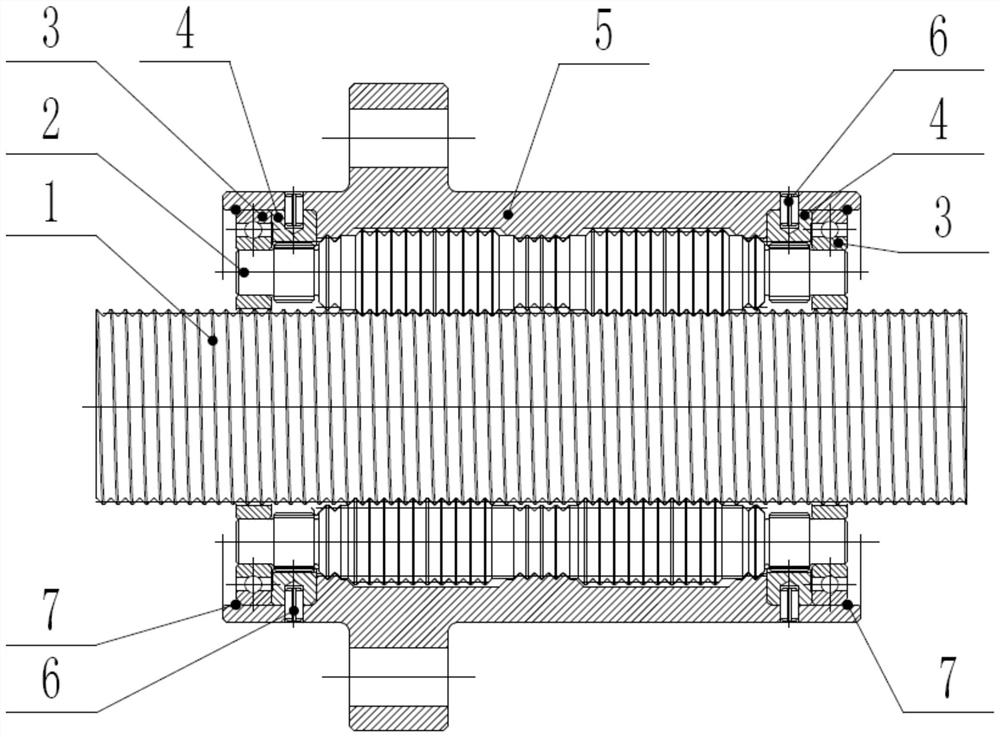
[0040] Such as figure 1 As shown, the planetary roller screw specifically includes a screw rod 1, two ring gears 4, a nut 5, two bearing cages 3, two wire lock rings 7, n rollers 2 and positioning pins 6; , the screw rod 1 is axially placed horizontally; n rollers 2 are evenly distributed on the outer wall of the screw rod 1 along the circumferential direction; the rollers 2 are threaded with the screw rod 1; the bearing cage 3 is a ring structure; 2 bearing cages 3 are...


PUM


Abstract

The invention relates to a planetary roller screw, belonging to the field of roller screw design; including screw, two inner ring gears, nuts, two bearing cages, two wire lock rings, n rollers and positioning pins ; n rollers are evenly distributed on the outer wall of the screw along the circumferential direction; two bearing cages are set on the outer wall of the screw; and the two bearing cages are respectively located at both axial ends of the roller; The two ends extend into two bearing cages respectively; the two internal ring gears are respectively set on the outer walls of the n rollers at both axial ends; the nuts are set on the outer walls of the n rollers; Solid connection; 2 steel wire lock rings are arranged at the axial outer end of the contact between the corresponding bearing cage and the nut; realize axial limit; the invention combines the characteristics of planetary gear transmission and thread transmission to convert rotational motion into linear motion.

Description

technical field [0001] The invention belongs to the field of roller screw design and relates to a planetary roller screw. Background technique [0002] Compared with ball screws, differential planetary roller screws have stronger bearing capacity, higher rigidity, simpler structure, and higher reliability, and are widely used in heavy-duty fields such as braking mechanisms and electromechanical servos. However, the differential planetary roller screw has the problem of unstable transmission ratio. The reason is that the movement and load are transmitted between the roller and the nut only by friction, without any rolling limiting mechanism, and are subject to manufacturing and assembly under load. Influenced by precision, etc., there will be a relative slip between the nut and the roller, resulting in a change in the transmission ratio of the planetary roller screw, making it impossible to achieve a fixed transmission ratio transmission. In the past, the effect of slip was ...

Claims


Application Information

Patent Timeline
Patent Type & Authority Patents(China)
IPC IPC(8): F16H37/12F16H25/22
CPCF16H37/124F16H25/2252
Inventor 侍威黄玉平郑继贵张兆晶徐强王水铭
Owner BEIJING RES INST OF PRECISE MECHATRONICS CONTROLS
Why Eureka
Try Eureka