Hydraulic rotary joint for excavator rotation

A technology of hydraulic rotation and excavator, which is applied in the direction of pipes/pipe joints/fittings, adjustable connections, mechanical equipment, etc., which can solve the effects of rotation and friction, hydraulic overflow, uncontrollable and avoidable problems, and achieve protection The effect of rotating the mandrel

Active Publication Date: 2020-10-16
山东恒旺集团有限公司
View PDF10 Cites 3 Cited by
  • Summary
  • Abstract
  • Description
  • Claims
  • Application Information

AI Technical Summary

Problems solved by technology

[0003] 1. When the hydraulic rotary joint is working, the concentricity must be ensured between the rotating mandrel and the fixed shell, but in practice, due to the work of the fuselage, different directions and different magnitudes of force will be generated, so that it is connected with the fuselage The rotating mandrel will be offset, and the rotating mandrel itself and the fixed shell are connected by a movable socket, which will cause the force between the rotating mandrel and the fixed shell to be affected by the force of the fuselage. The inclined deformation will affect the effect of rotation and friction if it is light, and it will cause mechanical damage between the two ends of the shaft core and the shell, so that the hydraulic pressure will overflow and cause a safety accident;
[0004] 2. The hydraulic rotary joint also transmits high hydraulic pressure during the rotation process. In actual use, the rotary joint is only responsible for rotation, so that when the hydraulic pressure is unstable, especially when the hydraulic pressure increases, the load at the rotary joint will be caused. Greatly increased, and the load of the flexible socket connection itself is greatly restricted, so that when the hydraulic pressure increases, the rescue will cause overload, which will cause safety hazards. At the same time, there will be impurities in the hydraulic medium. Impurities are also easy to accumulate at the socket, which will also cause an increase in load, and the existing hydraulic rotary joints cannot effectively control and avoid these situations at all.

Method used


Image

  • Hydraulic rotary joint for excavator rotation
  • Hydraulic rotary joint for excavator rotation
  • Hydraulic rotary joint for excavator rotation

Examples


Embodiment Construction

[0020] The following will clearly and completely describe the technical solutions in the embodiments of the present invention with reference to the accompanying drawings in the embodiments of the present invention. Obviously, the described embodiments are only some, not all, embodiments of the present invention. Based on the embodiments of the present invention, all other embodiments obtained by persons of ordinary skill in the art without making creative efforts belong to the protection scope of the present invention.

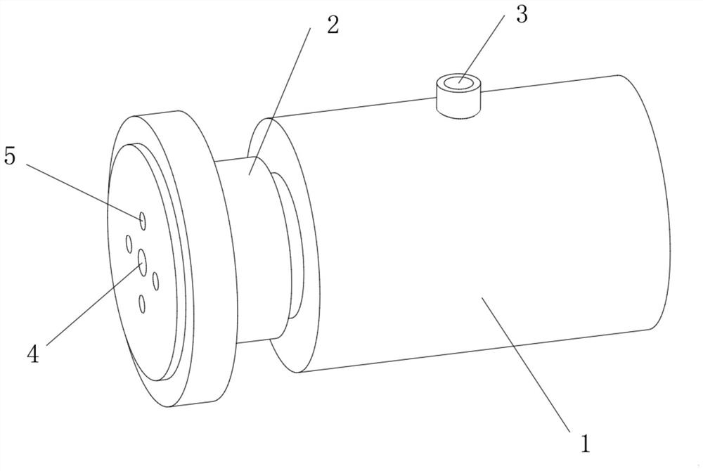
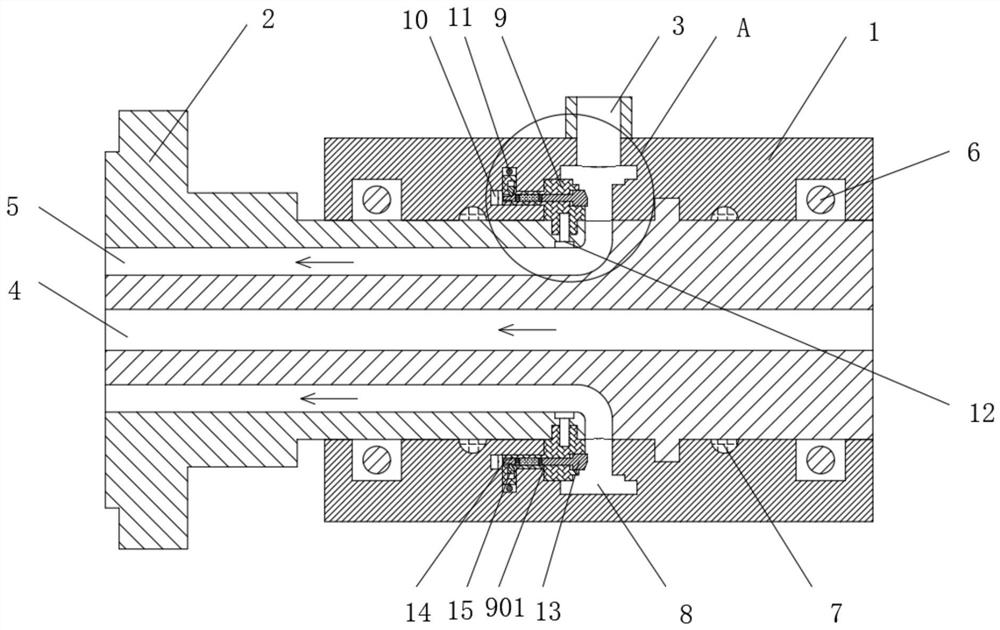
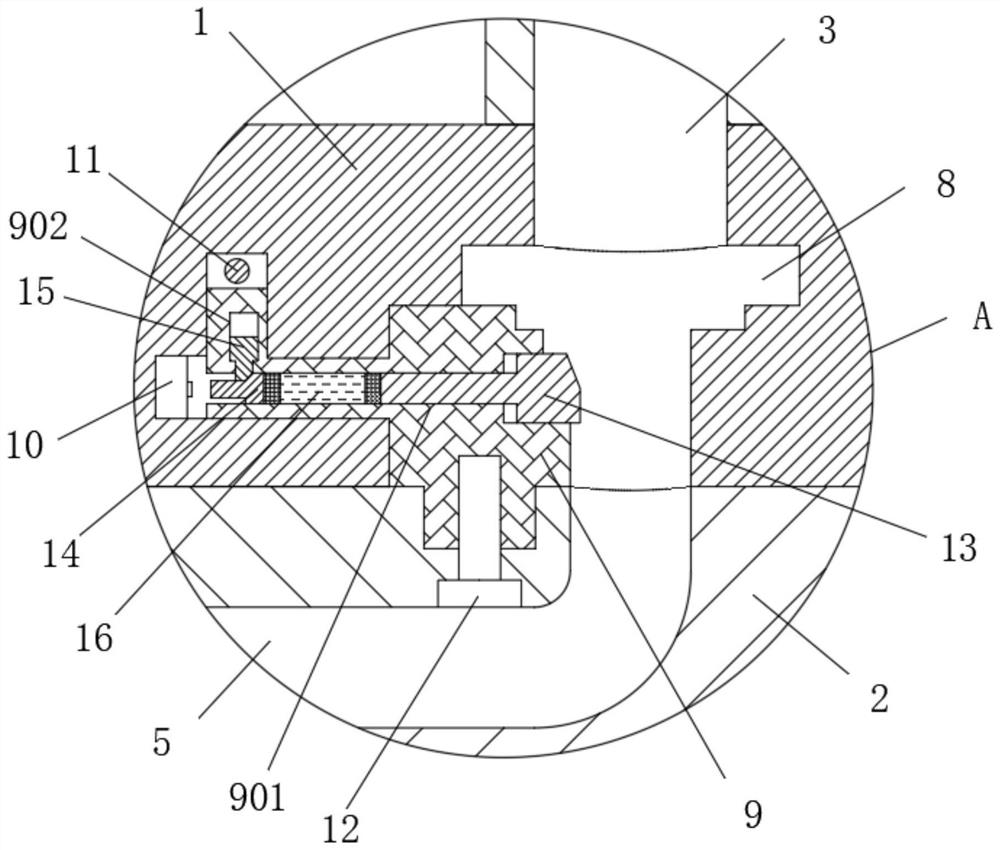
[0021] see Figure 1-4 , a hydraulic rotary joint for excavator rotation, comprising a fixed housing 1, the inner ring of the fixed housing 1 is movably sleeved with a rotating mandrel 2, the middle part of the top of the rotating mandrel 2 is provided with an oil inlet 3, and the rotating mandrel There is a through hole 4 in the middle of 2, and the outer ring of the rotating mandrel 2 located in the through hole 4 is provided with a hydraulic hole 5 in a rin...


PUM


Abstract

The invention relates to the technical field of rotary joints, and discloses a hydraulic rotary joint for excavator rotation. The hydraulic rotary joint for the excavator rotation comprises a fixing shell, a rotary mandrel movably is arranged with an inner ring of the fixing shell in a sleeve mode, an oil inlet is formed in the middle of the top of the rotary mandrel, a hydraulic hole annularly isformed in an outer ring of a through hole inside the rotary mandrel, an annular groove is formed in the position, located at the bottom of the oil inlet, inside the fixing shell and communicates withthe hydraulic hole, a stable lantern ring is movably connected to the position, located on one side of the annular groove, inside the fixing shell in a sleeve mode, an alarm apparatus is fixedly installed at the position, located on one side of the stable lantern ring, inside the fixing shell, and a through telescopic sliding hole is formed in the middle of the stable lantern ring. The stable lantern ring and the alarm apparatus are arranged in the fixing shell, a hydraulic adjusting head is connected into the stable lantern ring in a sleeve mode and matches with a switch to trigger an ejector rod and a limiting sliding block so that the rotary mandrel can be effectively protected against deviation, and the rotary joint is controlled to be used safely.

Description

technical field [0001] The invention relates to the technical field of rotary joints, in particular to a hydraulic rotary joint for excavator rotation. Background technique [0002] Excavator is a kind of mechanical equipment that is very commonly used nowadays. Compared with manpower, it can save a lot of time, and the operation of the excavator itself is not very complicated. It mainly uses the fuselage to control the bucket to dig and other actions. The rotating part between the body and the base is connected by a hydraulic rotary joint. This joint structure is simple and easy to use. The fixed shell of the outer ring is used to socket the internal rotating mandrel, and a groove and the rotating mandrel are opened on the shell. The through holes on the joint are always connected, so that oil can always be supplied through when rotating, but there are still some problems with this kind of rotary joint: [0003] 1. When the hydraulic rotary joint is working, the concentric...

Claims


Application Information

Patent Timeline
Patent Type & Authority Applications(China)
IPC IPC(8): F16L27/087G08B21/24
CPCF16L27/087G08B21/24
Inventor 付贤安
Owner 山东恒旺集团有限公司
Why Eureka
Try Eureka