An Inertial Sensor Based on Anti-Magnetic Levitation

An inertial sensor and diamagnet technology, applied in the field of inertial sensors, can solve problems such as energy dissipation and affect sensor performance, and achieve the effects of high measurement accuracy and low mechanical thermal noise

Active Publication Date: 2020-09-08
HUAZHONG UNIV OF SCI & TECH
View PDF6 Cites 0 Cited by
  • Summary
  • Abstract
  • Description
  • Claims
  • Application Information

AI Technical Summary

Problems solved by technology

[0004] Aiming at the defects of the prior art, the purpose of the present invention is to solve the technical problems of the existing gravitational acceleration sensor, which requires energy from the outside, direct contact between the spring and the mass block to generate friction, the friction force affects the performance of the sensor, and energy dissipation

Method used


Image

  • An Inertial Sensor Based on Anti-Magnetic Levitation
  • An Inertial Sensor Based on Anti-Magnetic Levitation

Examples


Embodiment Construction

[0031] In order to make the object, technical solution and advantages of the present invention clearer, the present invention will be further described in detail below in conjunction with the accompanying drawings and embodiments. It should be understood that the specific embodiments described here are only used to explain the present invention, not to limit the present invention. In addition, the technical features involved in the various embodiments of the present invention described below can be combined with each other as long as they do not constitute a conflict with each other.

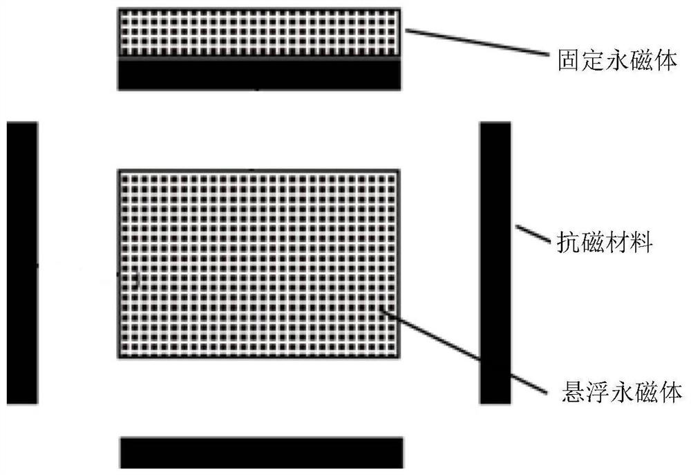
[0032] figure 1 It is a schematic diagram of an anti-magnetic levitation structure provided by an embodiment of the present invention; figure 1 As shown, including: fixed permanent magnet, diamagnetic material and suspended permanent magnet. The fixed permanent magnet is located directly above the suspended permanent magnet. The fixed permanent magnet provides the levitation force to overcome ...


PUM


Abstract

The invention discloses an inertial sensor based on anti-magnet suspension, comprising: an anti-magnet suspension structure comprising: a fixed permanent magnet, a suspended permanent magnet, a suspended permanent magnet protection structure and diamagnetic materials, wherein the fixed permanent magnet is fixed directly above the suspended permanent magnet for providing a suspension force for thesuspended permanent magnet, so as to overcome the gravity of the suspended permanent magnet, so that the suspended permanent magnet is suspended; the suspended permanent magnet protection structure islocated at the periphery of the suspended permanent magnet, and the diamagnetic materials are symmetrically fixed on a built-in surface of the suspended permanent magnet protection structure to provide symmetrical diamagnetic forces to limit the movement of the suspended permanent magnet; when the anti-magnet suspension structure is subjected to an external acting force, such that the position ofthe floating permanent magnet changes, a diamagnetic force acts as a quasi-elastic restoring force to constrain the position of the suspended permanent magnet; and an optical displacement sensor detects the displacement change of the suspended permanent magnet in the space to determine an external inertia acceleration. The inertial sensor disclosed by the invention solves the problems of the influence of the friction force of the existing gravity acceleration sensor and the energy dissipation.

Description

technical field [0001] The present invention relates to the technical field of inertial sensors, and more particularly, relates to an inertial sensor based on diamagnetic levitation. Background technique [0002] Near the surface, the earth's gravitational field is one of the most basic and important physical fields, which is of great significance to the precise measurement of the gravitational field. Gravity measurement has broad application prospects in resource exploration, auxiliary navigation, national defense and earth science. Taking the acceleration of gravity sensor as an example, the acceleration of gravity sensor is a precision gravity measurement sensor that measures small changes in the acceleration of gravity. [0003] The basic model of the mechanical structure of the acceleration of gravity sensor is a spring-oscillator structure, which is composed of a spring, a proof mass, and damping caused by air or structure. The proof mass is usually used as the core s...

Claims


Application Information

Patent Timeline
Patent Type & Authority Patents(China)
IPC IPC(8): G01V7/00G01V7/02G01P15/08G01P15/03G01P1/00
CPCG01P1/00G01P15/03G01P15/08G01P15/0802G01V7/00G01V7/02
Inventor 刘骅锋王秋罗鹏顺涂良成
Owner HUAZHONG UNIV OF SCI & TECH
Why Eureka
Try Eureka