Hydraulic rotary joint for excavator rotation

A hydraulic rotation and excavator technology, applied in the direction of pipes/pipe joints/fittings, adjustable connections, mechanical equipment, etc., can solve the effects of rotation and problems such as friction, overload, safety accidents, etc., to protect the rotating mandrel Effect

Active Publication Date: 2021-09-28
山东恒旺集团有限公司
View PDF10 Cites 0 Cited by
  • Summary
  • Abstract
  • Description
  • Claims
  • Application Information

AI Technical Summary

Problems solved by technology

[0003] 1. When the hydraulic rotary joint is working, the concentricity must be ensured between the rotating mandrel and the fixed shell, but in practice, due to the work of the fuselage, different directions and different magnitudes of force will be generated, so that it is connected with the fuselage The rotating mandrel will be offset, and the rotating mandrel itself and the fixed shell are connected by a movable socket, which will cause the force between the rotating mandrel and the fixed shell to be affected by the force of the fuselage. The inclined deformation will affect the effect of rotation and friction if it is light, and it will cause mechanical damage between the two ends of the shaft core and the shell, so that the hydraulic pressure will overflow and cause a safety accident;
[0004] 2. The hydraulic rotary joint also transmits high hydraulic pressure during the rotation process. In actual use, the rotary joint is only responsible for rotation, so that when the hydraulic pressure is unstable, especially when the hydraulic pressure increases, the load at the rotary joint will be caused. Greatly increased, and the load of the flexible socket connection itself is greatly restricted, so that when the hydraulic pressure increases, the rescue will cause overload, which will cause safety hazards. At the same time, there will be impurities in the hydraulic medium. Impurities are also easy to accumulate at the socket, which will also cause an increase in load, and the existing hydraulic rotary joints cannot effectively control and avoid these situations at all.

Method used


Image

  • Hydraulic rotary joint for excavator rotation
  • Hydraulic rotary joint for excavator rotation
  • Hydraulic rotary joint for excavator rotation

Examples


Embodiment Construction

[0020] Next, the technical solutions in the embodiments of the present invention will be apparent from the embodiment of the present invention, and it is clearly described, and it is understood that the described embodiments are merely embodiments of the present invention, not all of the embodiments. Based on the embodiments of the present invention, there are all other embodiments obtained without making creative labor without making creative labor premises.

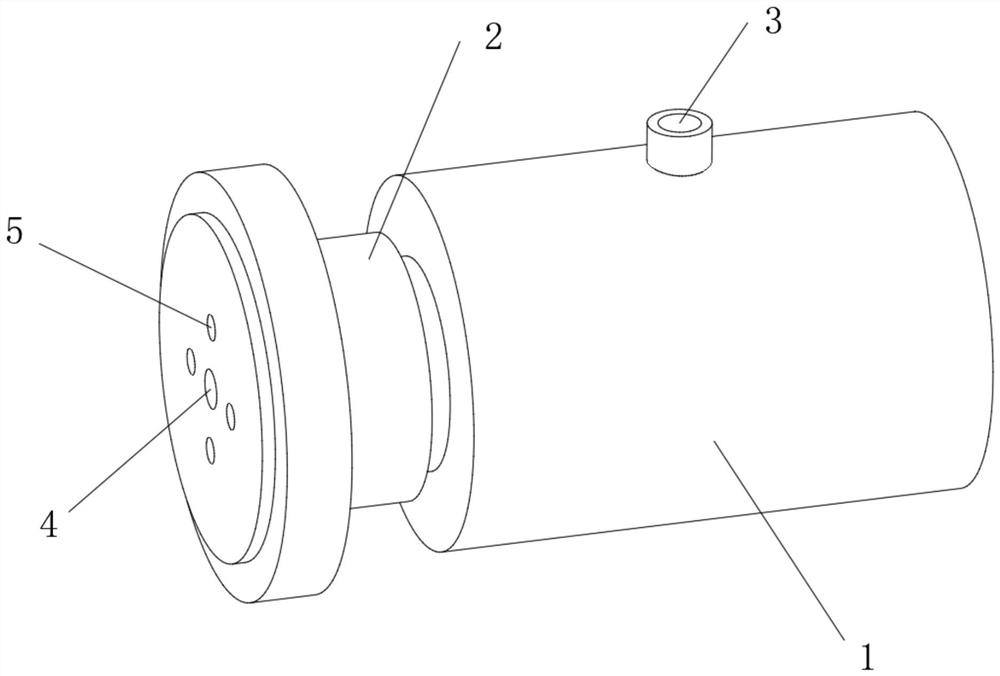
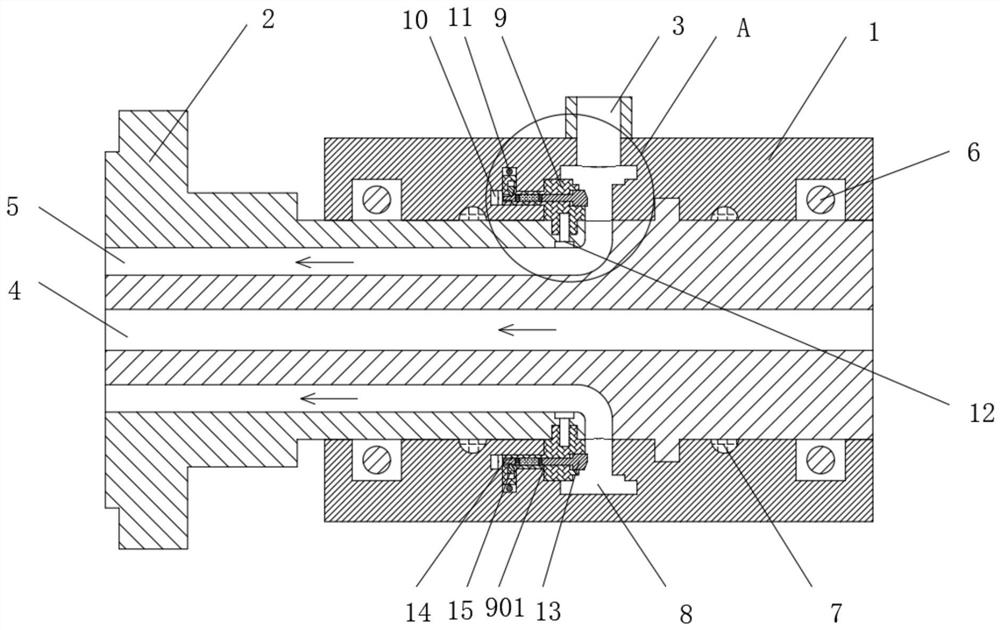
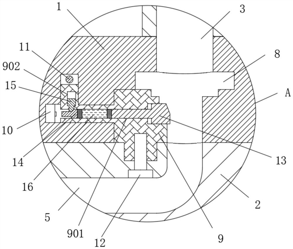
[0021] See Figure 1-4 An excavator is transferred by a hydraulic rotary joint comprising a fixing housing 1, an inner ring activity attached to the fixed housing 1, and a rotary core shaft 2, the central portion of the rotary core shaft 2 is opened 3, the rotary mandrel 2 The middle of the center is opened through the through hole 4, and the rotary core shaft 2 is located in an annular shape in which the outer ring of the through hole 4 is opened, and the rotary core shaft 2 and the outer ring fixed to the fixed housing 1 s...


PUM


Abstract

The invention relates to the technical field of rotary joints, and discloses a hydraulic rotary joint for excavator rotation, which includes a fixed housing, a rotating mandrel is movably sleeved on the inner ring of the fixed housing, and an oil inlet is provided in the middle of the top of the rotating mandrel. There is a hydraulic hole in the outer ring of the through hole inside the rotating mandrel, and an annular groove is opened inside the fixed housing at the bottom of the oil inlet, and the annular groove communicates with the hydraulic hole. The position on one side of the annular groove is movably socketed with a stable collar, and the inside of the fixed housing is fixedly installed with an alarm at the position on one side of the stable collar. It is equipped with a stable collar and an alarm in the fixed shell, and a hydraulic adjustment head is sleeved in the stable collar to cooperate with the switch to touch the ejector rod and the limit slider, which can effectively protect the rotating mandrel from deviation and control The swivel joint is safe to use.

Description

Technical field [0001] The present invention relates to the field of rotating joints, and is specifically an excavator transfer hydraulic rotary joint. Background technique [0002] Excavators are a mechanical equipment that is often used today. It can save a lot of time compared to manpower, and the operation of the excavator itself is not very complicated, mainly using the body control of the transfection and other action, machine The hydraulic rotary joint is connected to the rotating portion between the base, which is easy to use, and the rotary mandrel inside the inside of the fixed housing cover of the outer ring is opened, and the groove and rotary mandrel are opened on the housing. The on-hole is always connected, so that it can be passed at always oil at the time of rotation, but this rotary joint still has some problems: [0003] 1. The rotating mandrel and the fixed housing must be guaranteed by the rotary core and the fixed housing during the hydraulic rotary joint op...

Claims


Application Information

Patent Timeline
Patent Type & Authority Patents(China)
IPC IPC(8): F16L27/087G08B21/24
CPCF16L27/087G08B21/24
Inventor 付贤安
Owner 山东恒旺集团有限公司
Why Eureka
Try Eureka