Live pig slaughtering device

A kind of equipment and pig technology, applied in the field of slaughter, can solve the problems of unfavorable work for workers, reduced efficiency of pig slaughter, complicated operation, etc.

Inactive Publication Date: 2020-10-20
安徽永洁肉类有限公司
View PDF7 Cites 1 Cited by
  • Summary
  • Abstract
  • Description
  • Claims
  • Application Information

AI Technical Summary

Problems solved by technology

[0003] Pigs need to be slaughtered when they are in their prime, or when their weight no longer increases. At present, a single or a small number of pigs are slaughtered by manually fixing the pigs and slaughtering them. However, this method is difficult to operate and there are many problems. Big risk. When slaughtering pigs in batches, some pig slaughtering devices currently on the market need to kill pigs by electric shock and

Method used


Image

  • Live pig slaughtering device
  • Live pig slaughtering device
  • Live pig slaughtering device

Examples


Embodiment 1

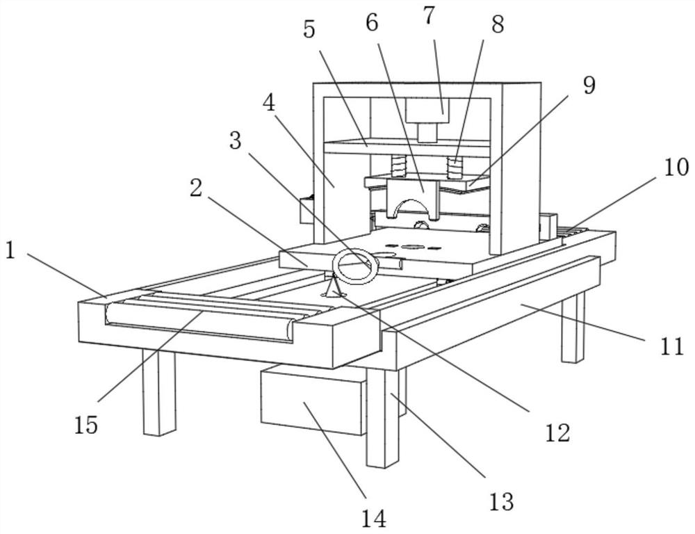
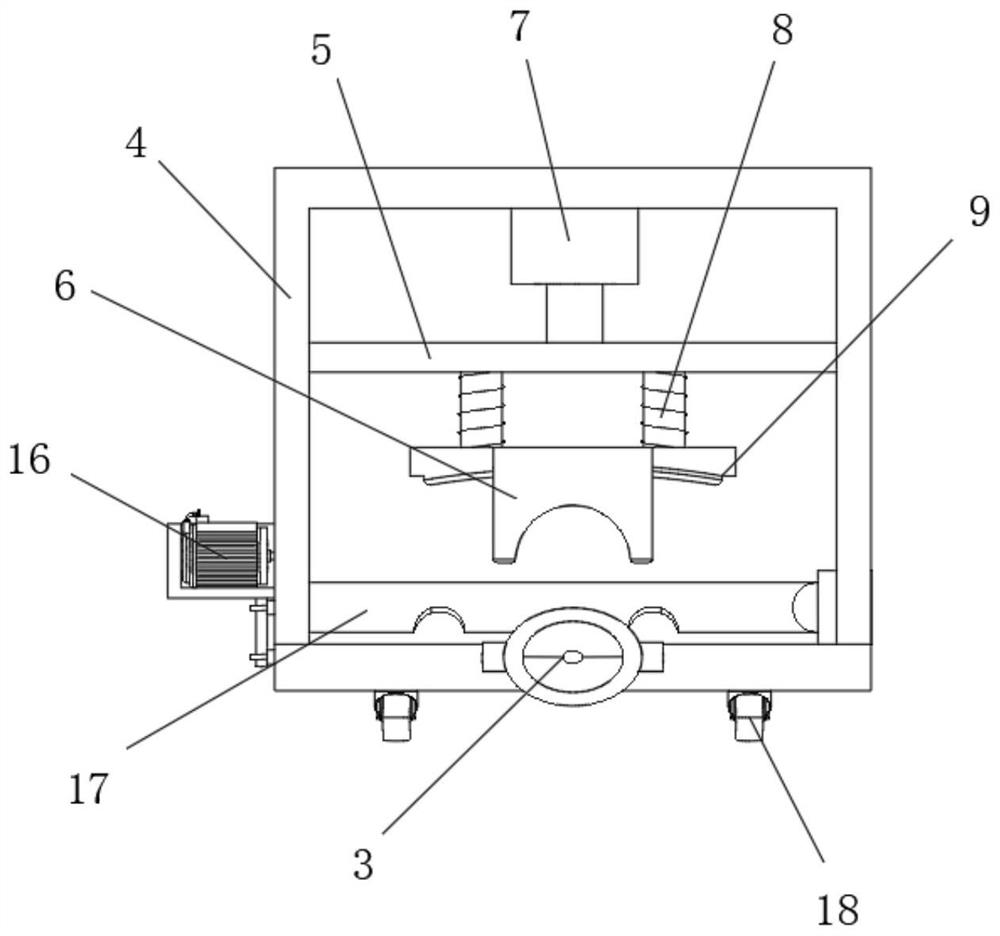
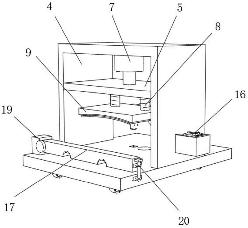
[0027] refer to Figure 1-4 , a pig slaughtering equipment, including a workbench 1, the top outer wall of the workbench 1 is provided with a chute, and the inner wall of the chute is slidably connected with a fixed seat 2, and the top outer wall of the fixed seat 2 is connected with a fixed frame 4 by screws, and The top inner wall of the fixed frame 4 is connected with the first hydraulic cylinder 7 by a rivet, and one end of the piston rod of the first hydraulic cylinder 7 is connected with the sliding plate 5 by a screw, and the outer wall of the bottom end of the sliding plate 5 is connected by two equidistant distributions by screws. connecting rod 8, and the bottom outer wall of connecting rod 8 is connected with body splint 9 by screw, and one side outer wall of body splint 9 is connected with head splint 6 by screw, one side outer wall of the top of fixed seat 2 The first rotating shaft is movably connected, and the outer wall of the first rotating shaft is sleeved wi...

Embodiment 2

[0034] refer to figure 1 , a kind of pig slaughtering equipment, compared with Embodiment 1, this embodiment also includes a first rectangular groove on the other side of the top of the workbench 1, and the inner wall of the first rectangular groove is movably connected with seven to nine Two equidistantly distributed feeding rollers 10, a side outer wall on the top of the workbench 1 is provided with a second rectangular groove, and the inwall of the second rectangular groove is movably connected with seven to nine equidistantly distributed discharge rollers 15.

[0035] Working principle: when the pig needs to be fed, the pig moves to the feed roller 10, and the feed roller 10 rotates to drive the pig forward. After the slaughter is completed, the pig moves from the fixed seat 2 to the discharge roller 15, and the discharge roller 15 The rotation drives the pig to move.


PUM


Abstract

The invention discloses a live pig slaughtering device. The live pig slaughtering device comprises a workbench, and is characterized in that a sliding groove is formed in the outer wall of the top endof the workbench, wherein a fixing base is slidably connected to the inner wall of the sliding groove; a fixing frame is connected to the outer wall of the top end of the fixing base through screws;a first hydraulic cylinder is connected to the inner wall of the top end of the fixing frame through rivets; a sliding plate is connected to one end of a piston rod of the first hydraulic cylinder through screws; two connecting rods distributed at equal intervals are connected to the outer wall of the bottom end of the sliding plate through screws; body clamping plates are connected to the outer walls of the bottom ends of the connecting rods through screws; and head clamping plates are connected to the outer walls of one sides of the body clamping plates through screws. According to the livepig slaughtering device, the body clamping plates clamp the body of a live pig, foot clamping plates fix pig feet through locking valves, a mouth sleeve rotatably sleeves the mouth of the live pig, the situation is avoided that noise is not beneficial to work of workers during live pig slaughtering, the live pig fixing difficulty is low, operation is easy, and the live pig slaughtering efficiencyis improved.

Description

technical field [0001] The invention relates to the technical field of slaughter, in particular to a pig slaughtering equipment. Background technique [0002] Pigs, that is, living pigs, are collectively referred to as domestic pigs other than breeding pigs that have not been slaughtered. Pigs, omnivores. Pigs generally refer to livestock. The pig is the end of the zodiac, also known as Hai. Mammals have stout bodies, short limbs, and long snouts. The meat is edible, the skin can be tanned, the body is fat and the limbs are short, the nature is gentle, the adaptability is strong, easy to raise, and the reproduction is fast. There are black, white, sauce red or black and white flowers and other colors. Pigs can be bred 5-12 months after birth, and the gestation period is about 4 months. The average lifespan of a pig is 20 years. [0003] Pigs need to be slaughtered when they are in their prime, or when their weight no longer increases. At present, a single or a small nu...

Claims


Application Information

Patent Timeline
IPC IPC(8): A22B1/00A22B5/04A22B5/06A22B7/00
CPCA22B1/00A22B5/04A22B5/06A22B7/001
Inventor 于万龙
Owner 安徽永洁肉类有限公司
Why Eureka
Try Eureka