Multi-functional stretcher
A multi-functional, stretcher technology, applied in the field of medical equipment, can solve the problem of single function of the stretcher
- Summary
- Abstract
- Description
- Claims
- Application Information
AI Technical Summary
Problems solved by technology
Method used
Image

Examples
Embodiment 1
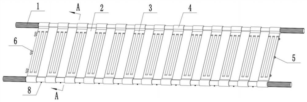
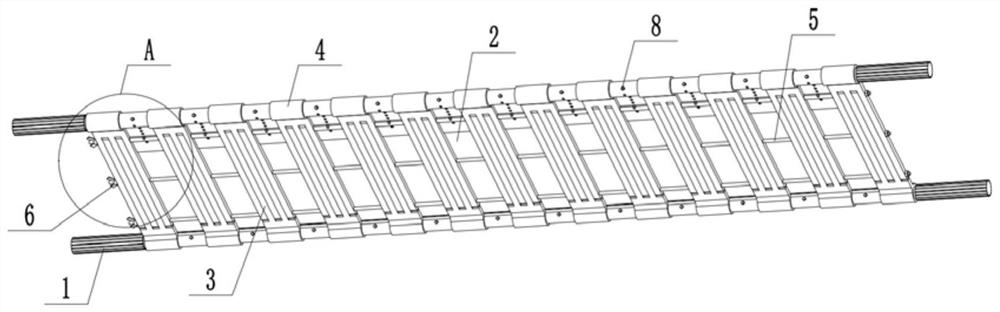
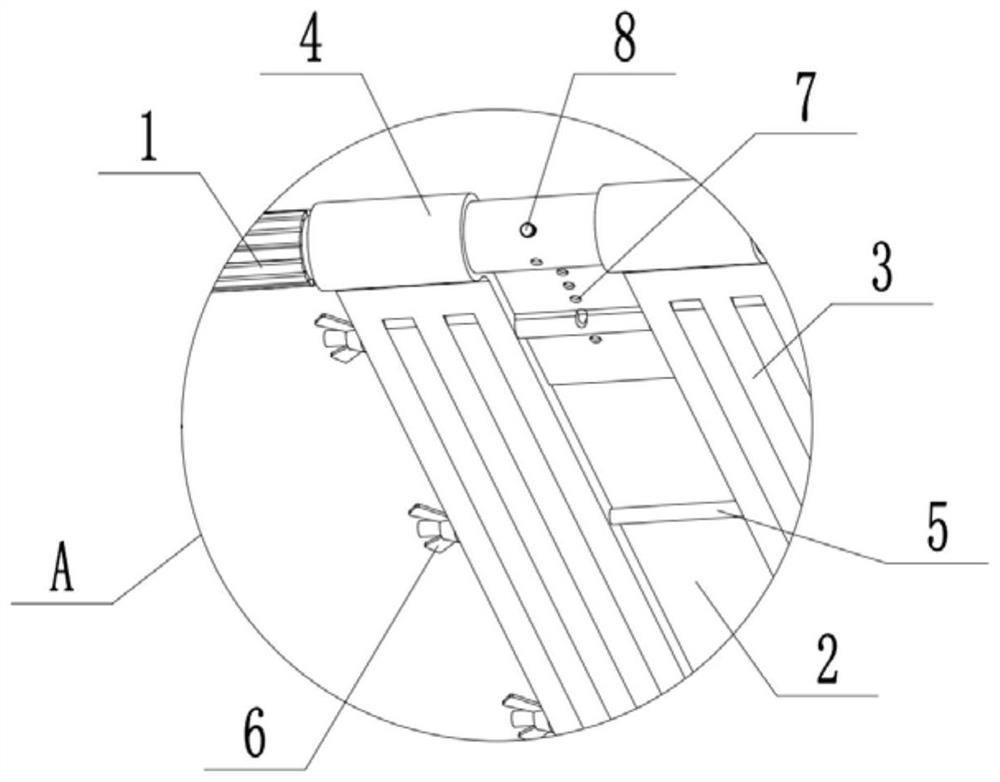
[0042] Embodiment one is basically as attached figure 1 , figure 2 , image 3 , Figure 4 and Figure 5 Shown: a multi-functional stretcher, including two load-bearing rods 1 arranged in parallel in the left and right directions, and a plurality of supports connected between the two load-bearing rods 1 and a plurality of retaining cloths 2 are detachably connected, the retaining cloth 2 and the support members Staggered along the length direction of the bearing rod 1, in order to facilitate the medical staff to stably grasp the bearing rod 1, anti-skid parts are provided at both ends of the bearing rod 1. In this embodiment, the anti-slip parts include 1 Non-slip thread on the outer wall of the end.
[0043] combine figure 1 and Figure 5 As shown, the support includes two support plates 3 with the same shape and size, the two support plates 3 are located between the two load-bearing rods 1 and the two support plates 3 are welded with a sleeve 4 near one end of the corr...
Embodiment 2
[0052] The difference between embodiment two and embodiment one is: as Image 6 As shown, in this embodiment, a stop frame 9 is provided above the load-bearing rod 1, and the stop frame 9 includes a cross bar 901 and an insertion rod 902 welded to both ends of the cross bar 901. There are blind holes arranged vertically downward, and the distance between the two blind holes is equal to the distance between the two insertion rods 902 on the blocking frame 9, so that the insertion rods 902 can be inserted into the insertion holes. In this embodiment, the insertion rod 902 is connected to the blind hole in the same way as the locking rod 5 and the placement hole in Embodiment 1, so as to prevent the insertion rod 902 from being easily pulled out after being inserted into the blind hole.
[0053]In this embodiment, a cross bar 901 is set above the bearing bar 1, and the shielding effect of the cross bar 901 is used to prevent the wounded on the stretcher from turning sideways on t...
Embodiment 3
[0055] The difference between embodiment three and embodiment two is: as Figure 8 As shown, the sleeve 4 is provided with a first through hole 10 and a second through hole 11. When the two support plates 3 in the same support member rotate to the same plane, the first through hole 10 is aligned with the blind hole, so that the insertion When the rod 902 is inserted into the blind hole, it also passes through the first through hole 10; when the two support plates 3 in the same support member rotate to Figure 7 In the intersecting state, the second through hole 11 is aligned with the blind hole, so that the insertion rod 902 also passes through the second through hole 11 when inserted into the blind hole.
[0056] In this embodiment, by setting the first through hole 10 and the second through hole 11 on the sleeve 4, when the two support plates 3 in the same support member are rotated to the same plane or to a crossed state, the insertion rod 902 Inserted into the blind hole,...
PUM
 Abstract
Description
Claims
Application Information
 - R&D
- Intellectual Property
- Life Sciences
- Materials
- Tech Scout
- Unparalleled Data Quality
- Higher Quality Content
- 60% Fewer Hallucinations
Browse by: Latest US Patents, China's latest patents, Technical Efficacy Thesaurus, Application Domain, Technology Topic, Popular Technical Reports.
© 2025 PatSnap. All rights reserved.Legal|Privacy policy|Modern Slavery Act Transparency Statement|Sitemap|About US| Contact US: help@patsnap.com