Luggage cloth winding device

A technology for fabric rolls and bags, which is used in transportation and packaging, coiling strips, and thin material handling, etc., can solve problems such as lack of fixtures, hidden dangers, and increased safety.

Inactive Publication Date: 2020-10-20
胡晓珍
View PDF0 Cites 2 Cited by
  • Summary
  • Abstract
  • Description
  • Claims
  • Application Information

AI Technical Summary

Problems solved by technology

[0002] The process of fabric processing is inseparable from the application of the winding device, and the amount of winding of a single roll of fabric is certain, and the winding must be restarted after reaching a certain level, but the existing winding device is lacking at the beginning of winding. For the fixing device of the cloth, it needs to be manually p

Method used


Image

  • Luggage cloth winding device
  • Luggage cloth winding device
  • Luggage cloth winding device

Examples


Embodiment 1

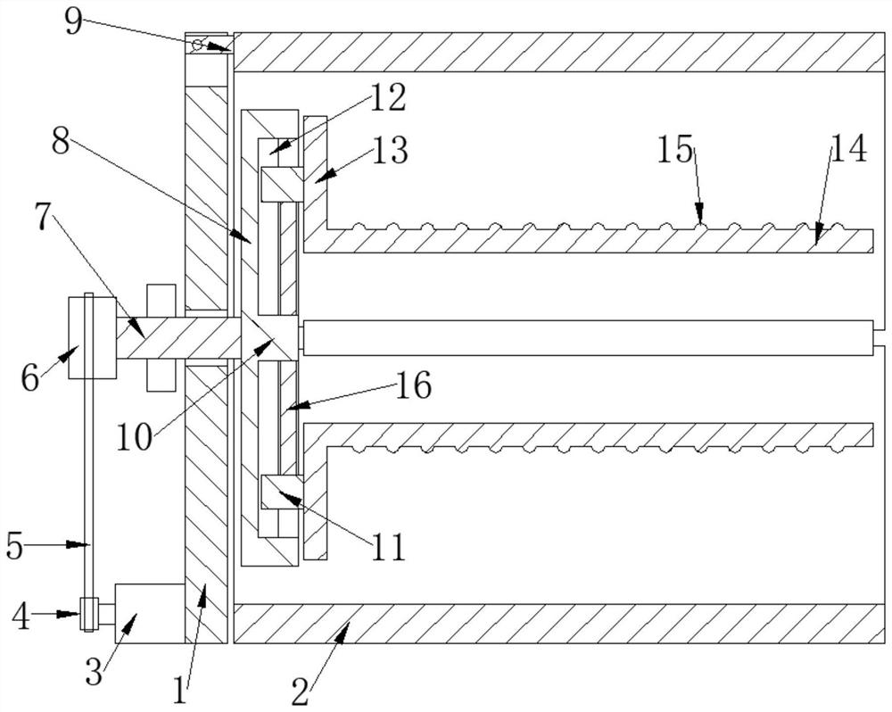
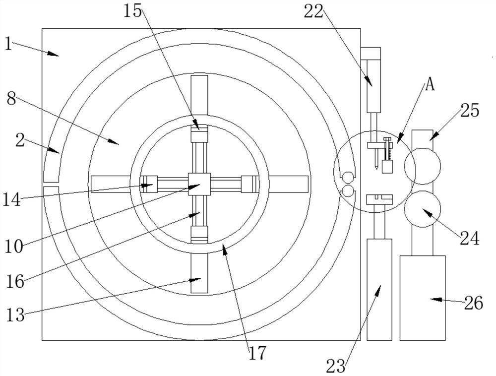
[0025] see Figure 1-6 , the present embodiment provides a bag fabric rolling device, including a fixed frame 1, a guide transfer structure and a rotating disk 8, the guide transfer structure includes a fixed support leg 26, the support leg 26 is fixedly connected with a mounting Rod 25, two guide rollers 24 for guiding and transferring are arranged on the mounting rod 25, the transmission shaft 7 is fixedly connected to the rotating disk 8, and the transmission shaft 7 runs through the fixed frame 1, so The side of the rotating disk 8 is provided with a number of cloth roller brackets, the cloth roller bracket includes a sliding block 11, a vertical strut 13 and a horizontal strut 14, and the side of the rotating disk 8 is provided with a number of "T" shaped sliding grooves 12 , the sliding block 11 is slidably disposed in the sliding groove 12, the vertical strut 13 is fixedly connected to the sliding block 11, and the horizontal strut 14 is fixedly connected to the vertica...

Embodiment 2

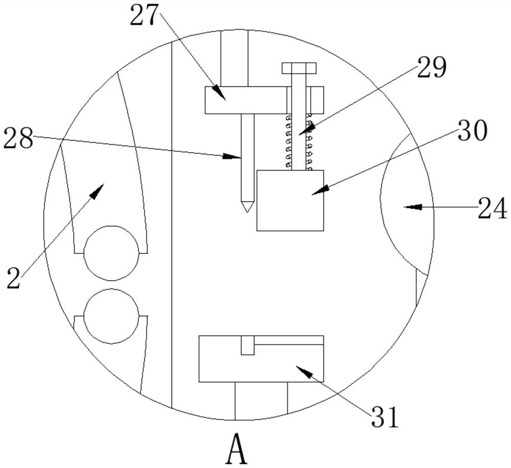
[0036] see figure 2 and image 3 , on the basis of Embodiment 1, a sliding bar 29 is slidably arranged on the cutting frame 27, and the lower end of the sliding bar 29 is fixedly connected with a cover pressing bar 30, and the sliding bar 29 is located between the cutting frame 27 and the cover pressing bar 30. The positions between are provided with compression springs, the position of the lowest point of the cover pressure strip 30 is lower than the position of the lowest point of the cutting knife 28, and the cutting table 31 is provided with the cutting knife 28 and the cover pressure strip 30. Corresponding gap, by being provided with cover bead 30 and described cover bead 30 contacts cloth first, can cut off after cloth is suppressed, makes incision more neat, and described cover bead 30 can not rise automatically, so that Catch the cloth head in the process of changing the cloth roll 17, and then control it to rise.


PUM


Abstract

The invention discloses a luggage cloth winding device, and relates to the field of winding devices. An upper half drum is turned over, cloth winding rollers sleeve a plurality of horizontal support rods, the horizontal support rods always have outward tension under the action of a spring I, the cloth winding rollers can be fixed, a cloth head is pulled to a fixed notch, a fixing mechanism and thecloth head are pressed to the fixed notch to achieve fixation, the horizontal support rods are provided with outer circular surfaces, and the outer circular surfaces are provided with rolling columnswith plastic washers, so that the cloth winding rollers can easily move forwards in the direction of the horizontal support rods, but the degree of freedom perpendicular to the rotation of the horizontal support rods is limited by the resistance provided by the plastic washers, after completion, the fixing mechanism is pulled out through a pull-out ring and replaced with a new cloth winding roller, and a lifting mechanism is arranged on supporting legs, so that the height of guide rollers are adjustable, and the use is more convenient.

Description

technical field [0001] The invention relates to the technical field of coiling devices, in particular to a luggage cloth coiling device. Background technique [0002] The process of fabric processing is inseparable from the application of the winding device, and the amount of winding of a single roll of fabric is certain, and the winding must be restarted after reaching a certain level, but the existing winding device is lacking at the beginning of winding. For the fixing device of the cloth, it needs to be manually pressed to form a layered overlay before the rapid winding can be started. This method is inefficient on the one hand, and on the other hand, there is increased safety in the process of pressing it with the cloth roller and rotating it. Hidden dangers, therefore, now provide a kind of luggage cloth roll material device, can replace the new cloth roll safely and quickly. Contents of the invention [0003] The object of the present invention is to provide a bag ...

Claims


Application Information

Patent Timeline
IPC IPC(8): B65H19/30B65H23/26B65H18/10
CPCB65H18/10B65H19/30B65H23/26
Inventor 胡晓珍
Owner 胡晓珍
Why Eureka
Try Eureka