

Tool structure
a tool head and tool head technology, applied in the field of tool head structure, can solve the problems of prone dangerous to replace the tool head, and the fully opened tool head b>9/b> tends to drop down and hurt people, so as to improve the tool head structure, save strength, and easily replace the tool head
- Summary
- Abstract
- Description
- Claims
- Application Information
AI Technical Summary
Benefits of technology
Problems solved by technology
Method used
Image

Examples
Embodiment Construction
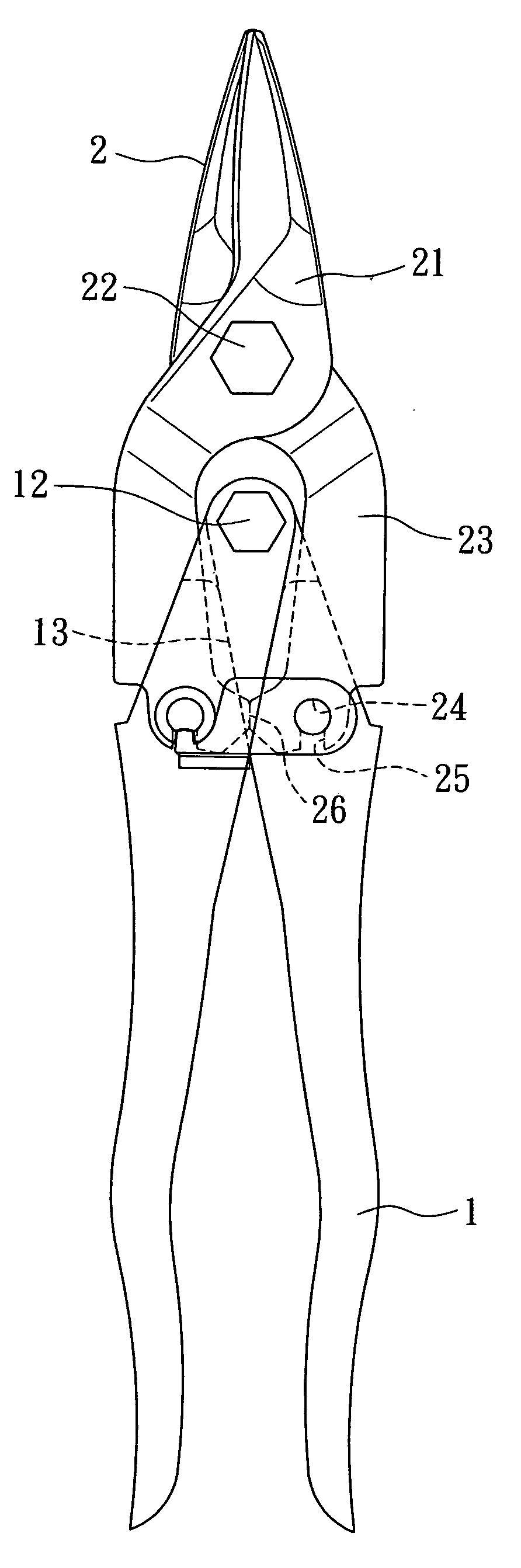
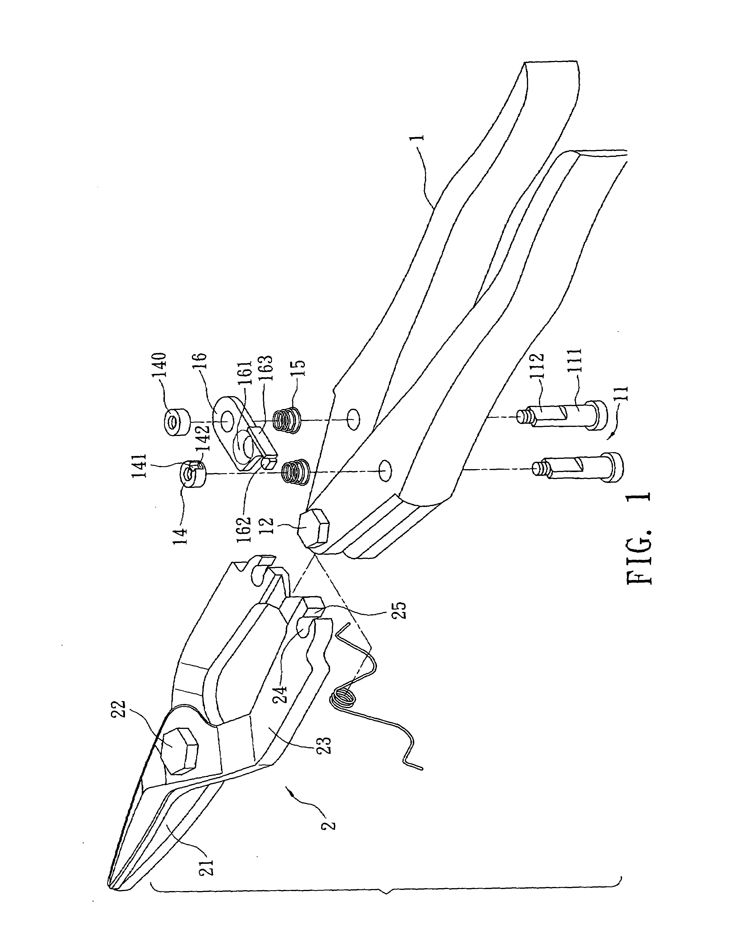
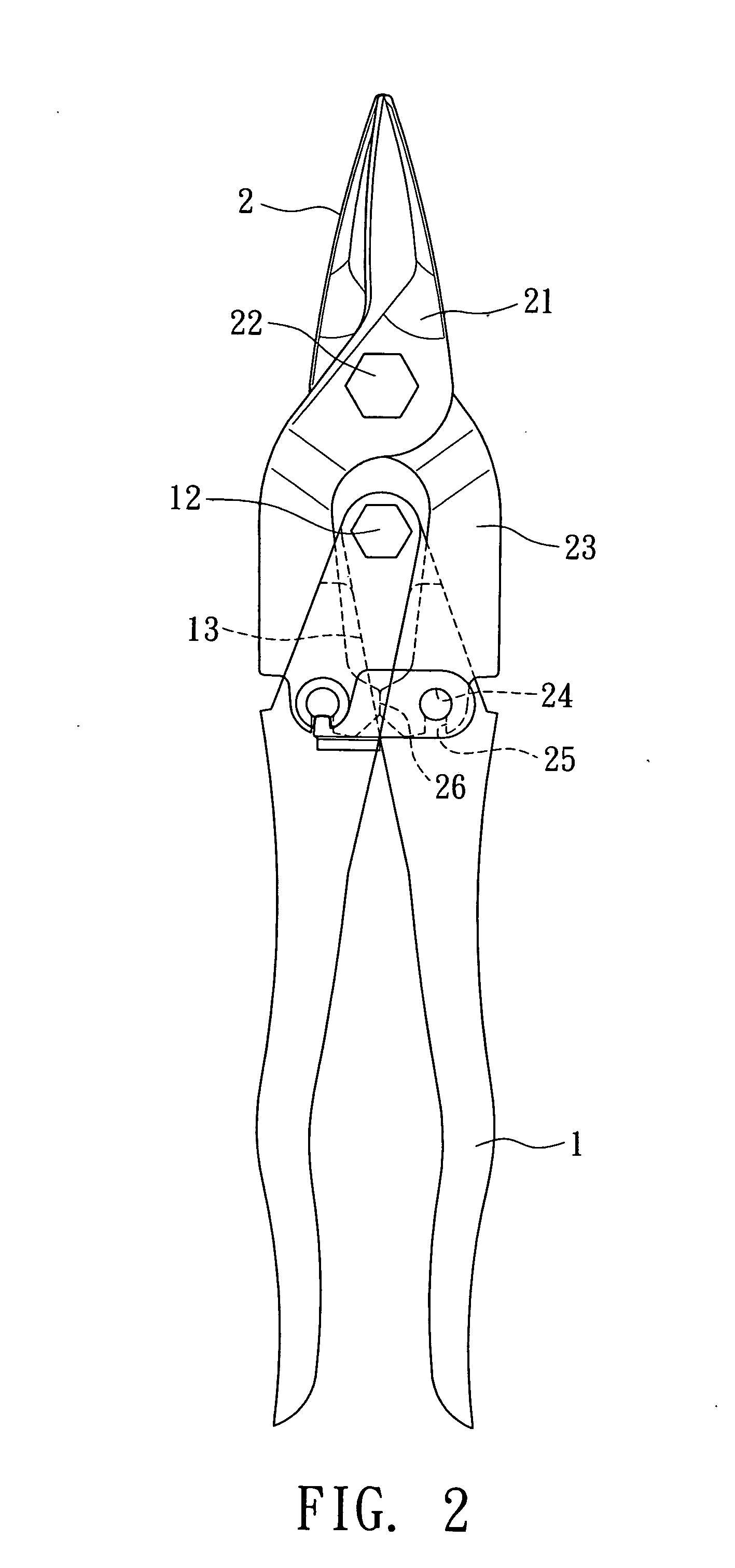
[0024]Please refer to FIGS. 1 to 5. The tool structure of the present invention includes two handles 1 pivotally connected with each other via a handle pivot shaft 12. A pin member 11 is fitted through each handle 1 in parallel to the handle pivot shaft 12. The pin members 11 can be forced to axially move within the handles 1. Each pin member 11 has a large diameter section 111 and a small diameter section 112. The large diameter section 111 has a diameter larger than the diameter of the small diameter section 112. The small diameter section 112 is fitted through the handle 1 to protrude from the handle 1. A stopper member 14, 140 is fixed with the protruding end of the small diameter section 112 protruding from the handle 1. In this embodiment, the large diameter section 111 of the pin member 11 is cylindrical, while the cross-section of the small diameter section 112 of the pin member 11 has two long sections 113 and two short sections 114. The distance between the long sections 1...
PUM
 Abstract
Description
Claims
Application Information