Apparatus and system for concrete surface repair and method

a concrete surface and apparatus technology, applied in the direction of single unit paving, building repair, etc., can solve the problems of significant negative impact on the compaction of the roadbed base, time-consuming and costly process, failure of the concrete surface to be replaced, etc., to reduce the time required, simplify the replacement of the failed concrete surface, and reduce the cost

Inactive Publication Date: 2008-11-11
DRAKE WILLIAM M
View PDF6 Cites 12 Cited by
  • Summary
  • Abstract
  • Description
  • Claims
  • Application Information

AI Technical Summary

Benefits of technology

[0014]It is, therefore, an object of the present invention to repair concrete surfaces without impacting the supporting sub-surface base.
[0015]It is another object of the present invention to mechanically guide the replacement concrete slab precisely into proper position in the concrete surface space to be filled including, but not limited to, surrounding unaffected concrete surfaces and relative to the underlying supporting roadbed.
[0016]It is yet another object of the present invention to decrease the time required to replace failed concrete surfaces over the art.
[0017]It is still yet another object of the present invention to decrease the costs associated with replacing failed concrete surfaces over the art.
[0018]A further object of the present invention is to simplify replacement of failed concrete surfaces and to do so more safely.
[0019]Yet another object of the present invention is to minimize the disruption of regular traffic flow attendant to replacement of failed concrete surfaces.

Problems solved by technology

Due to unforeseen traffic volume, traffic weights beyond the surface design specifications, and age, these concrete surfaces are failing.
Once failure occurs, replacement of the failed section of concrete surface is a necessary, time consuming, and costly process.
Present impact removal methods, such as use of jack-hammers or jack-hammers attached to front-end arms of Bob-cat type equipment, often have significant negative impact on the roadbed base compaction, leaving the replacement section inadequately supported.
On-site, poured concrete replacement methods in the art require lengthy downtime of the highway system.
Fast setting concrete formulations present added transportation and application costs and are expensive in themselves.
They are unpredictable and sensitive to slight climactic variations.
Occasionally delays such as traffic congestion cause the concrete to set up in the cement mixing truck in transit.

Method used


Image

  • Apparatus and system for concrete surface repair and method
  • Apparatus and system for concrete surface repair and method
  • Apparatus and system for concrete surface repair and method

Examples


Embodiment Construction

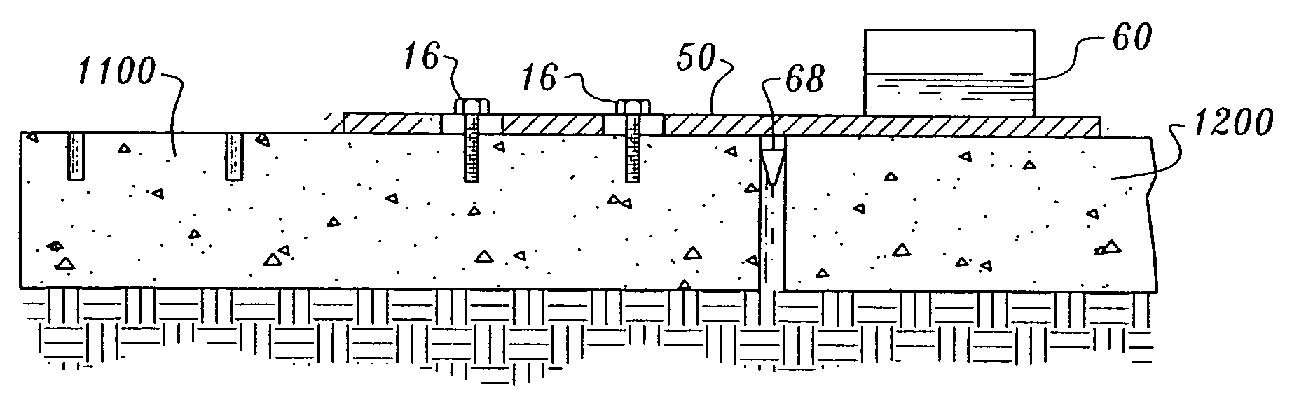
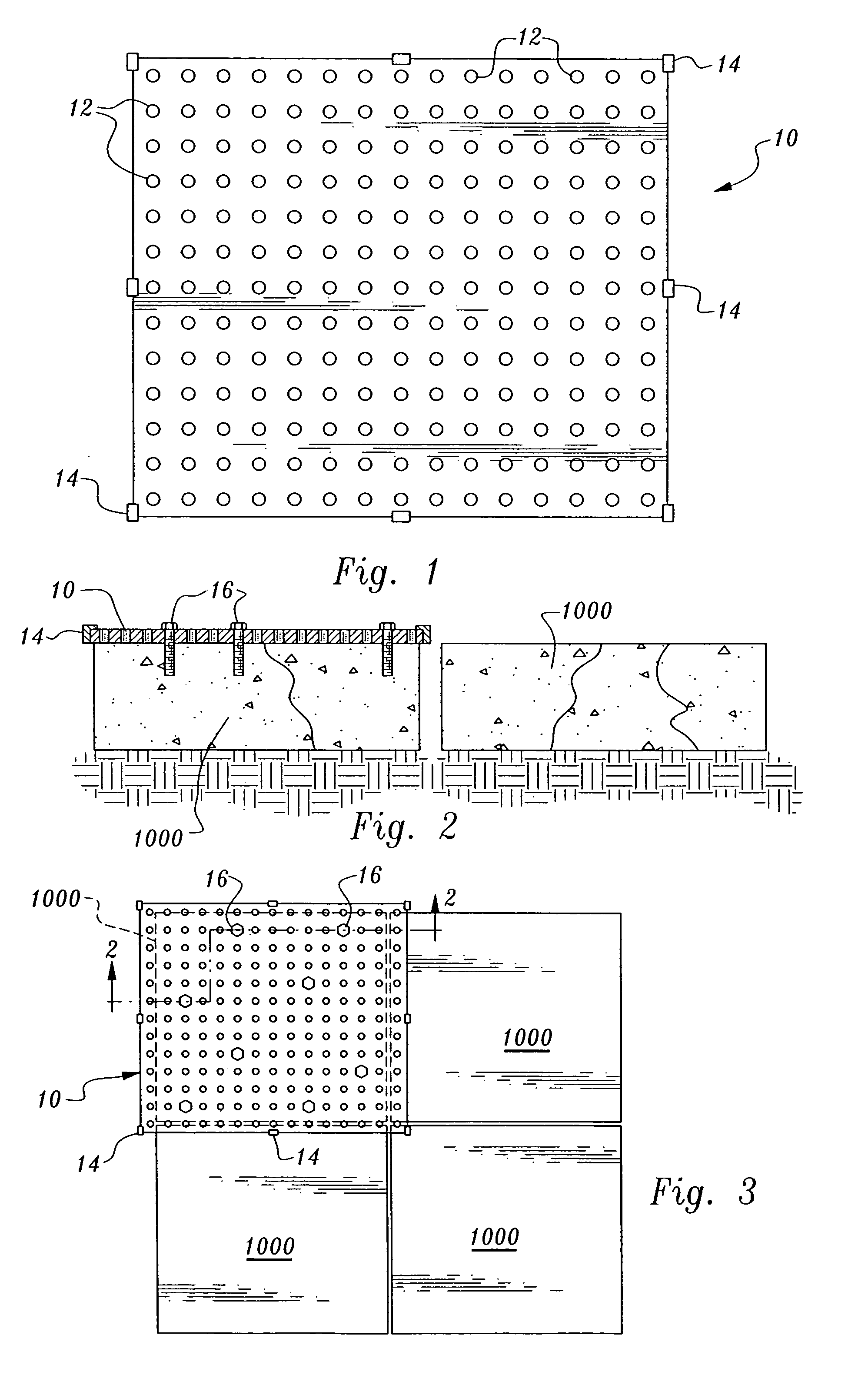
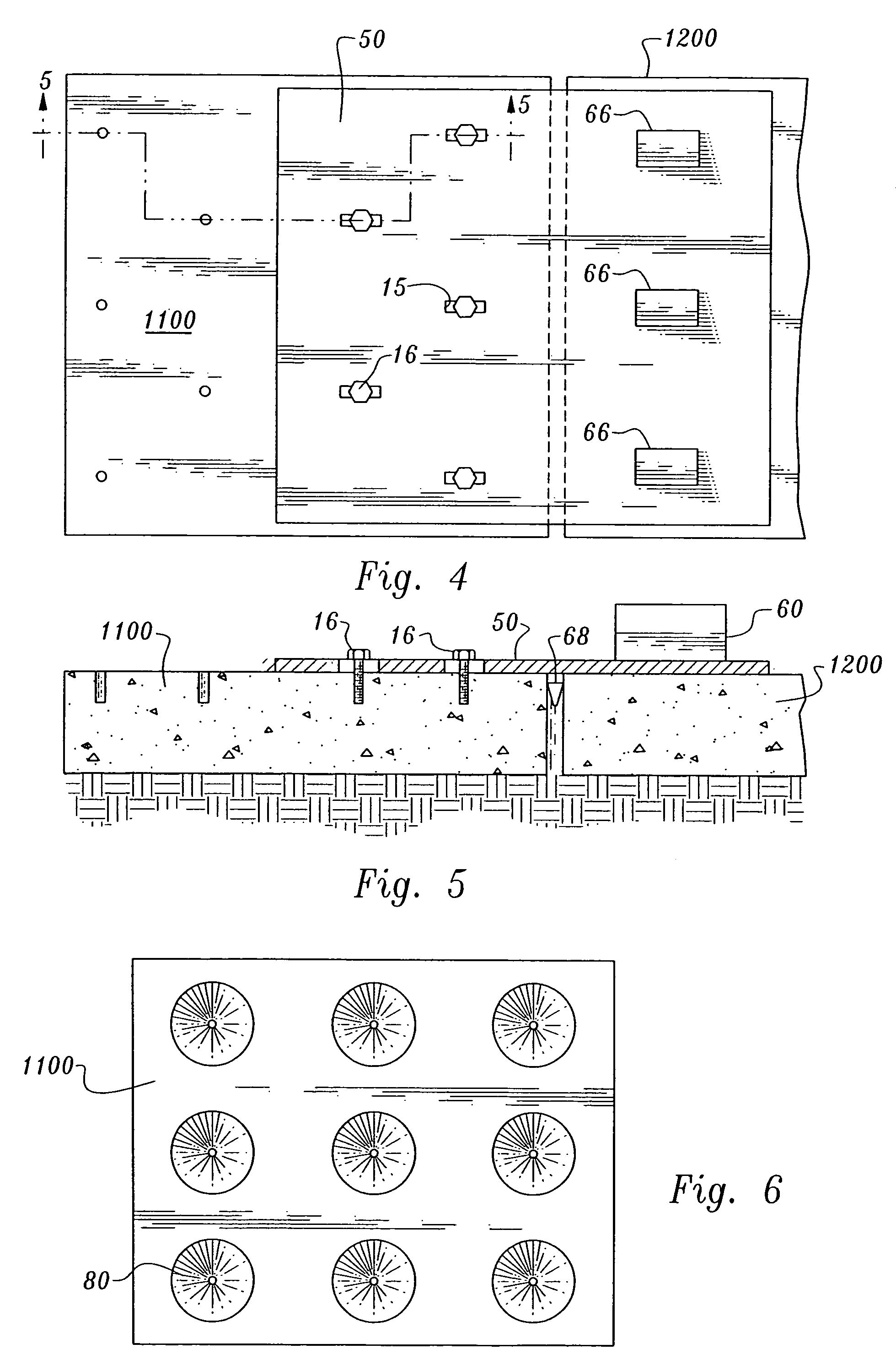
[0056]The apparatus and system of a preferred mode of the present invention removes broken concrete surface slabs in four lifts or less. As shown in FIG. 1, an embodiment of the present invention uses a rectangular broken concrete slab removal plate 10 approximately 7 feet by 8 feet, or slightly larger than a quarter section of highway slab. The removal plate 10 can be various sizes or geometries, even as large as an entire highway slab. The removal plate 10 is made of solid material comprising a substantially uniform thickness, plate edge boundaries, a planar plate top surface and a planar plate bottom surface. The rectangular removal plate 10 of the 7 feet by 8 feet dimension of this embodiment is a block of material, such as metal, high strength poly-carbon, or the like, thick and strong enough to support weights of approximately 5 tons for removal of quarter-cut concrete slabs.

[0057]The removal plate 10 further comprises a plurality of small diameter openings or holes 12 drilled...


PUM


Abstract

System and apparatus for repair of concrete surfaces, and a method of using the same, having slab removal plates, slab replacement plates, slab transport/replacement frame carrier vehicles, slab injection/guide collars for application of fluid binding material as support for the replacement slabs, and microprocessor controlled global satellite coordinates, wireless transmission, and bar code identification for slab replacement.

Description

CROSS-REFERENCES TO RELATED APPLICATIONS[0001]This U.S. non-provisional patent application is based upon and claims the filing date of U.S. provisional patent application Ser. No. 60 / 462,798 filed Apr. 14, 2003.STATEMENT REGARDING FEDERALLY SPONSORED RESEARCH OR DEVELOPMENT[0002]None.REFERENCE TO A MICRO-FICHE APPENDIX[0003]None.BACKGROUND OF THE INVENTION[0004]1. Field of the Invention[0005]The present invention relates to an improved apparatus and system, and methods for use of the same, for quick and cost effective, non-impact removal of failed concrete surfaces, and replacement of the failed sections using embodiments of suspension bridge-plates, carriers, and guide / grout injection collars to repair damaged highways built of concrete slabs or pre-cast concrete slabs.[0006]Using the system of plates and carrier of the present invention, a crew of possibly as few as two individuals could quickly and safely remove damaged slabs and replace the removed slabs with new, pre-cast concr...

Claims


Application Information

Patent Timeline
Patent Type & Authority Patents(United States)
IPC IPC(8): E04F15/22E01C7/14E01C19/52E01C23/12
CPCE01C7/147E01C19/52E01C23/0933E01C23/121
Inventor DRAKE, WILLIAM M.
Owner DRAKE WILLIAM M
Why Eureka
Try Eureka