
Steel plate hoisting structure for steel structure

A lifting structure and steel structure technology, applied in the direction of load hanging components, transportation and packaging, etc., can solve the problem that the safety and convenience of the restraint device cannot be well combined

Inactive Publication Date: 2020-10-20
李凯龙
View PDF5 Cites 1 Cited by
  • Summary
  • Abstract
  • Description
  • Claims
  • Application Information

AI Technical Summary

Problems solved by technology

[0002] In the process of steel plate conveying in the air in the prior art, the steel plate is transported to the designated construction site through the lifting device, which improves the construction efficiency. Specifically, the fixed connection of the steel plate is realized by connecting the restraint device at the end of the cable of the lifting device. Ordinary The restraint device cannot well meet the actual needs of construction, and the safety and convenience of the restraint device cannot be well combined

Method used


Image

  • Steel plate hoisting structure for steel structure
  • Steel plate hoisting structure for steel structure
  • Steel plate hoisting structure for steel structure

Examples


Embodiment Construction

[0018] The following will clearly and completely describe the technical solutions in the embodiments of the present invention with reference to the accompanying drawings in the embodiments of the present invention. Obviously, the described embodiments are only some, not all, embodiments of the present invention. Based on the technical solutions in the present invention, all other embodiments obtained by persons of ordinary skill in the art without making creative efforts belong to the protection scope of the present invention.

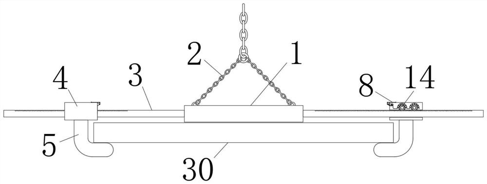
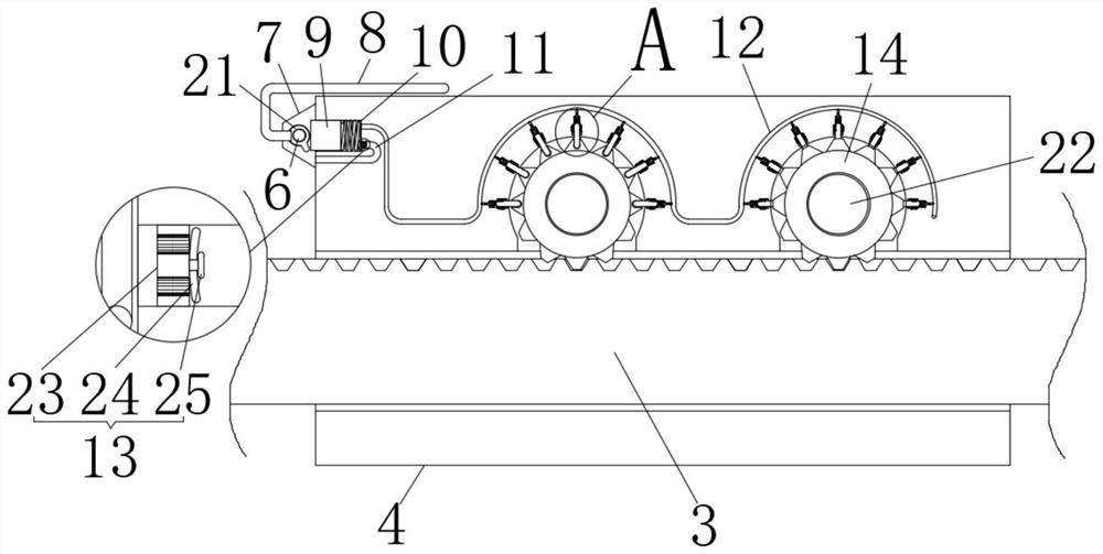
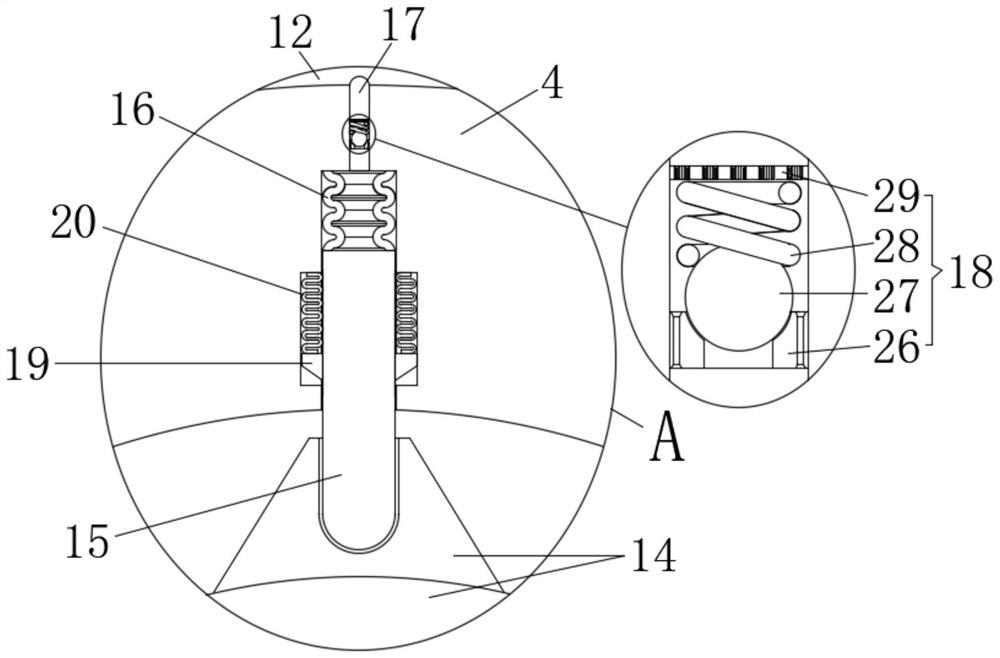
[0019] see Figure 1 to Figure 3 , the present invention provides a technical solution: a steel plate lifting structure for the use of steel structures, including a horizontal plate 1, a rope 2, a prismatic rod 3, a sliding seat 4 and an L-shaped plate 5, the horizontal plate 1 is in the shape of a square plate, and the horizontal plate The upper end of 1 is connected with a rope 2, and the side wall of the horizontal plate 1 is fixedly connected with ...


PUM


Abstract

The invention relates to the technical field of steel plate hoisting, in particular to a steel plate hoisting structure for a steel structure. The steel plate hoisting structure comprises a transverseplate, a rope, prism rods, sliding seats and L-shaped plates. The transverse plate is in a square plate shape. The rope is connected to the upper end of the transverse plate. The two prism rods in symmetrical distribution are fixedly connected to the side wall of the transverse plate. Each sliding seat is arranged on the corresponding prism rod. Each prism rod penetrates a platelike hole formed in the corresponding sliding seat. Each L-shaped plate is fixedly connected to the lower end of the corresponding sliding seat. A push seat is arranged at one side of each sliding seat. A central shaftis arranged on each push seat in a penetrating manner. A side lug plate is fixedly connected to the end of each central shaft. By means of the steel plate hoisting structure, the fast hoisting work for a partition plate is achieved; a worker only needs to manually pull pull rods, and position adjustment can be conducted on the sliding seats; after a while, the prism rods and the sliding seats restore to the clamping state automatically, and the partition plate can be quickly clamped between the two L-shaped plates; and the steel plate hoisting structure is easy, convenient and fast to operate, and the construction efficiency is improved.

Description

technical field [0001] The invention relates to the technical field of steel plate lifting, in particular to a steel plate lifting structure for steel structures. Background technique [0002] In the process of steel plate conveying in the air in the prior art, the steel plate is transported to the designated construction site through the lifting device, which improves the construction efficiency. Specifically, the fixed connection of the steel plate is realized by connecting the restraint device at the end of the cable of the lifting device. Ordinary The restraint device cannot well meet the actual needs of construction, and the safety and convenience of the restraint device cannot be well combined. [0003] If a steel plate hoisting restraint device can be invented, the firm connection of the steel plates can be quickly realized through simple operations, and the problem can be solved. For this reason, we provide a steel plate lifting structure for steel structures. Cont...

Claims


Application Information

Patent Timeline
IPC IPC(8): B66C1/16
CPCB66C1/16
Inventor 李凯龙
Owner 李凯龙
Learn More