Marble slab surface grooving machine

A marble slab and slotting machine technology, which is applied in stone processing tools, stone processing equipment, work accessories, etc., can solve the problems of slow slotting speed, laborious movement of marble, heavy marble, etc. Effect

Inactive Publication Date: 2021-09-07
杨丽
View PDF0 Cites 0 Cited by
  • Summary
  • Abstract
  • Description
  • Claims
  • Application Information

AI Technical Summary

Problems solved by technology

[0005] In order to overcome the disadvantages that the workers hold the cutting knife to slot the marble, the slotting speed is slow, and the marble is heavy, and it is difficult for the workers to move the marble when slotting. The technical problem to be solved is: to provide a convenient Marble slab surface grooving machine that moves marble and can quickly groove marble

Method used


Image

  • Marble slab surface grooving machine
  • Marble slab surface grooving machine
  • Marble slab surface grooving machine

Examples


Embodiment 1

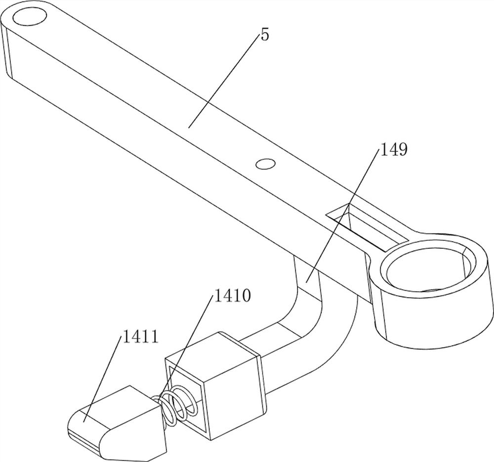
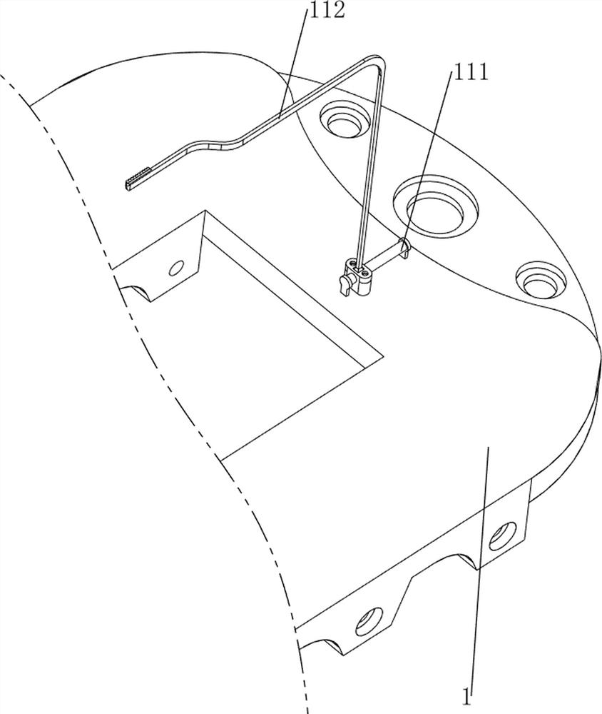
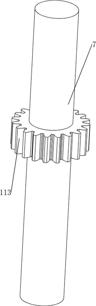
[0030] A marble slab surface groove machine, such as Figure 1-5 As shown, it includes a support plate 1, a first support frame 2, a first rotating shaft 3, a first slide rail 4, a first movable plate 5, a first spring 6, a second rotating shaft 7, a connecting rod 8, an electric saw 9, The manual sliding mechanism 10 and the rotating mechanism 11, the first support frame 2 is provided on the top rear side of the support plate 1, and the first support frame 2 is provided with the first rotating shaft 3 in the middle of the rotating type, and the first sliding rail is connected to the lower side of the first rotating shaft 3 4. The sliding type of the first sliding rail 4 is provided with a first movable plate 5, the first spring 6 is connected between the first movable plate 5 and the first sliding rail 4, and the front side of the first movable plate 5 is rotated with a second movable plate. Two rotating shafts 7, the lower side of the second rotating shaft 7 is provided with...

Embodiment 2

[0035] On the basis of Example 1, such as figure 1 , Figure 6 , Figure 7 , Figure 8 , Figure 9 and Figure 10As shown, an automatic sliding mechanism 12 is also included, and the automatic sliding mechanism 12 includes a second support frame 121, a motor 122, a third support frame 123, a third rotating shaft 124, a second gear 125 and a second rack 126, and the support plate 1. A second support frame 121 is provided on the right rear side of the top, and a motor 122 is provided on the second support frame 121. A third support frame 123 is provided in the middle of the rear side of the top of the support plate 1. The third support frame 123 is rotatably provided with a second support frame 123. Three rotating shafts 124, the third rotating shaft 124 is connected with the output shaft of the motor 122 through a coupling, the left and right sides of the bottom of the first sliding plate 103 are provided with second racks 126, and the left and right sides of the third rota...


PUM


Abstract

The invention relates to a grooving machine, in particular to a marble slab surface grooving machine. The technical problem to be solved is to provide the marble slab surface grooving machine which facilitates moving of marble and can rapidly groove the marble. The marble slab surface grooving machine comprises a supporting plate, a first supporting frame, a first rotating shaft, a first sliding rail, a first movable plate, a first spring, a connecting rod and electric saws; the first supporting frame is arranged at one side of the top of the supporting plate, the first rotating shaft is rotationally arranged in the middle of the first supporting frame, and the first sliding rail is connected to the lower side of the first rotating shaft; and the first movable plate is arranged in the first sliding rail in a sliding manner, the first spring is connected between the first movable plate and the first sliding rail, and the two electric saws are arranged on the connecting rod. According to the marble slab surface grooving machine, the effects of conveniently moving the marble and rapidly grooving the marble are achieved; and the first movable plate and the electric saws move downwards, so that the electric saws can quickly cut the marble.

Description

technical field [0001] The invention relates to a slotting machine, in particular to a slotting machine for the surface of a marble plate. Background technique [0002] Marble is mainly used as a carving and building material, and is often used in the construction of monuments, paving floors, walls, and carved railings. [0003] When people need to use marble slabs for decoration, they need to further process the marble according to the decoration requirements. If the marble needs to be grooved, the workers generally place the marble on the workbench, and then hold the cutting knife to groove the marble. After the completion, the marble is then removed. This way of grooving the marble makes the grooving speed slower and the marble is heavier. When the worker is grooving, it is more difficult to move the marble. [0004] Therefore, it is necessary to design a marble slab surface slotting machine that is convenient to move marble and can quickly slot the marble. Contents of...

Claims


Application Information

Patent Timeline
Patent Type & Authority Applications(China)
IPC IPC(8): B28D1/08B28D7/00B28D7/02
CPCB28D1/08B28D7/00B28D7/02
Inventor 杨丽
Owner 杨丽
Why Eureka
Try Eureka