
Installation structure and construction method of pipeline rotary compensator on large area of ​​water

A technology of rotating compensator and installation structure, which is applied in the direction of pipeline laying and maintenance, transportation and packaging, pipe/pipe joint/pipe fitting, etc., which can solve problems such as limited working range, achieve high safety, save construction cost, and operate strong effect

Active Publication Date: 2020-07-28
CHINA MCC17 GRP
View PDF5 Cites 0 Cited by
  • Summary
  • Abstract
  • Description
  • Claims
  • Application Information

AI Technical Summary

Problems solved by technology

The conventional installation method of the rotary compensator is: use a 25t truck crane to hoist the rotary compensator directly to the designated position for welding; however, when the pipeline passes through a large area of ​​water, due to the limited working range of the truck crane, it is impossible to install it close to the rotary compensator location for hoists

Method used


Image

  • Installation structure and construction method of pipeline rotary compensator on large area of ​​water
  • Installation structure and construction method of pipeline rotary compensator on large area of ​​water
  • Installation structure and construction method of pipeline rotary compensator on large area of ​​water

Examples


Embodiment Construction

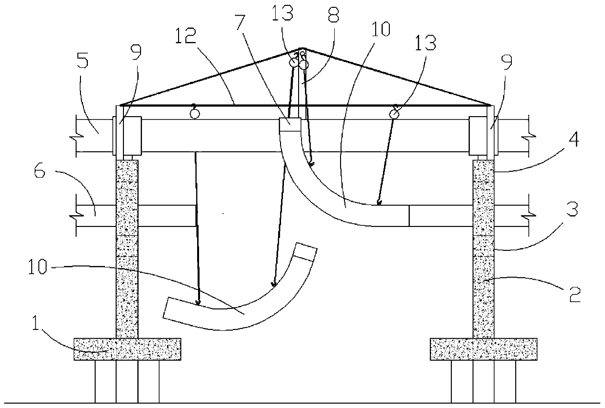
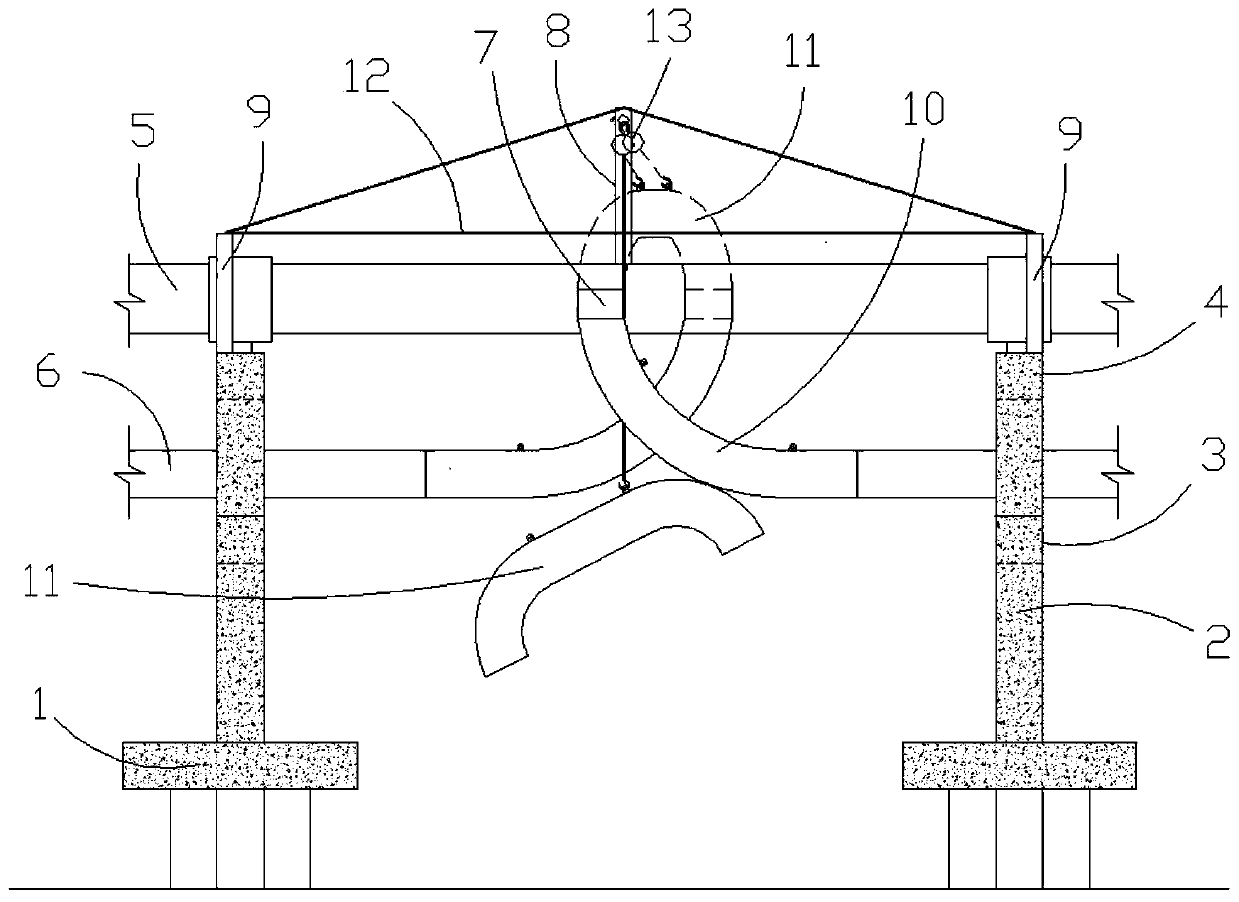
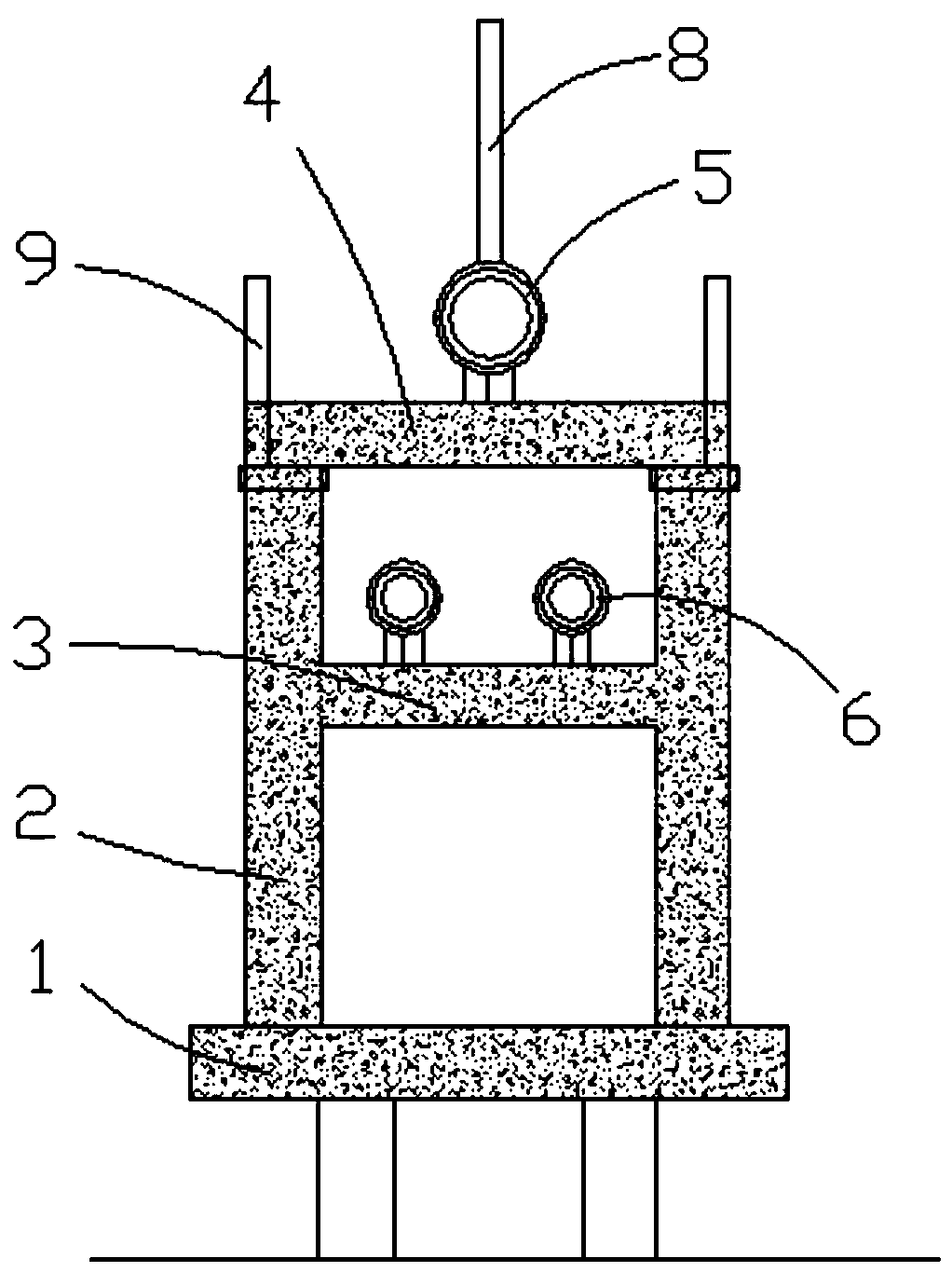
[0024] The present invention will be described in further detail below in conjunction with accompanying drawing, so that those skilled in the art can understand more clearly, as figure 1 and figure 2 As shown, the installation structure of the pipeline rotary compensator on the large-area water area of ​​the present invention includes: two pile caps 1 on the water; concrete supports are respectively fixed on the two pile caps 1, and the concrete supports include a pair of columns 2, The connecting beam 3 and the top beam 4, the lower ends of the two columns 2 are fixed on the pile cap 1, the two ends of the top beam 13 are fixed on the upper ends of the two columns 11, the connecting beam 3 below the top beam 4 The two ends are fixed on the column 2; the main heating pipe 5 is fixed on the top beam 4 of the concrete support through the pipe support, and there are two pairs of auxiliary heating pipes 6 below the main heating pipe 5. The pipe 6 is fixed on the connecting beam ...


PUM


Abstract

The invention discloses a mounting structure of a rotary compensator for pipelines on a large-area water domain and a construction method thereof, and relates to the technical field of pipeline construction. The mounting structure of the rotary compensator comprises two pile support platforms; concrete supports are separately fixed to the pile support platforms; a main heat supply pipeline and twoauxiliary heat supply pipes are arranged on the concrete supports; a first support upright column is fixed to the main heat supply pipeline; two pairs of second support upright posts are fixed to theconcrete support; a longitudinally-horizontal steel wire rope and a transversely-horizontal steel wire rope are separately connected between the top ends of the two pairs of second support upright posts; the rotary compensator is welded fixedly to one end of a first elbow; a plurality of suspending lugs are fixed to the first elbow and a second elbow; a plurality of reversible chains are suspended at the top end of the first support upright post; a plurality of reversible chains are suspended on the transversely-horizontal steel wire rope positioned between the second support upright posts; and suspension operations of the first elbow and the second elbow are sequentially carried out through the reversible chains. According to the mounting structure of the rotary compensator for the pipelines on the large-area water domain disclosed by the invention, a suspension operation of the rotary compensator for the pipelines can be quickly carried out, so that the construction is simple and convenient, the operability is strong and the security is high.

Description

technical field [0001] The invention relates to the technical field of pipeline construction, in particular to an installation structure and a construction method for a pipeline rotary compensator on a large-area water area. Background technique [0002] During the use of municipal heating pipelines, when the temperature of the medium transported by the pipeline is different, or when the transmission is stopped for inspection and repair, the metal pipeline will be stretched and deformed due to the large temperature, which will damage the pipeline or pipeline accessories. Therefore, during the construction of municipal heating pipelines, compensation devices will be installed in sections of the pipeline to coordinate deformation, and rotary compensators are often used for rotating devices. The conventional installation method of the rotary compensator is: use a 25t truck crane to hoist the rotary compensator directly to the designated position for welding; however, when the p...

Claims


Application Information

Patent Timeline
Patent Type & Authority Patents(China)
IPC IPC(8): F16L1/12B66C13/08
CPCB66C13/08F16L1/12
Inventor 林涛姚海施光涛胡德帅
Owner CHINA MCC17 GRP
Learn More