
Lime soil filling construction method

A construction method and filling technology, which can be applied to buildings, roads, roads, etc., can solve the problems of high maintenance cost, high price, and difficulty in compensating for the inconsistency of the depth of new and old tools.

Active Publication Date: 2020-10-20
CHINA MCC17 GRP
View PDF4 Cites 2 Cited by
  • Summary
  • Abstract
  • Description
  • Claims
  • Application Information

AI Technical Summary

Problems solved by technology

The mixing depth is generally carried out manually. After the road mixer has mixed the mixture, use an iron mill to check the mixing depth. There are also mixers with automatic depth control for mixing depth control, but the price is relatively high. expensive
The automatic control device for mixing depth is an electronic structure, and the sensor will often fail due to the size of the soil clods during mixing, and the maintenance cost is expensive. At the same time, it is difficult for the automatic control device to compensate for the inconsistency of the depth between the old and new tools.

Method used


Image

  • Lime soil filling construction method
  • Lime soil filling construction method
  • Lime soil filling construction method

Examples


Embodiment 1

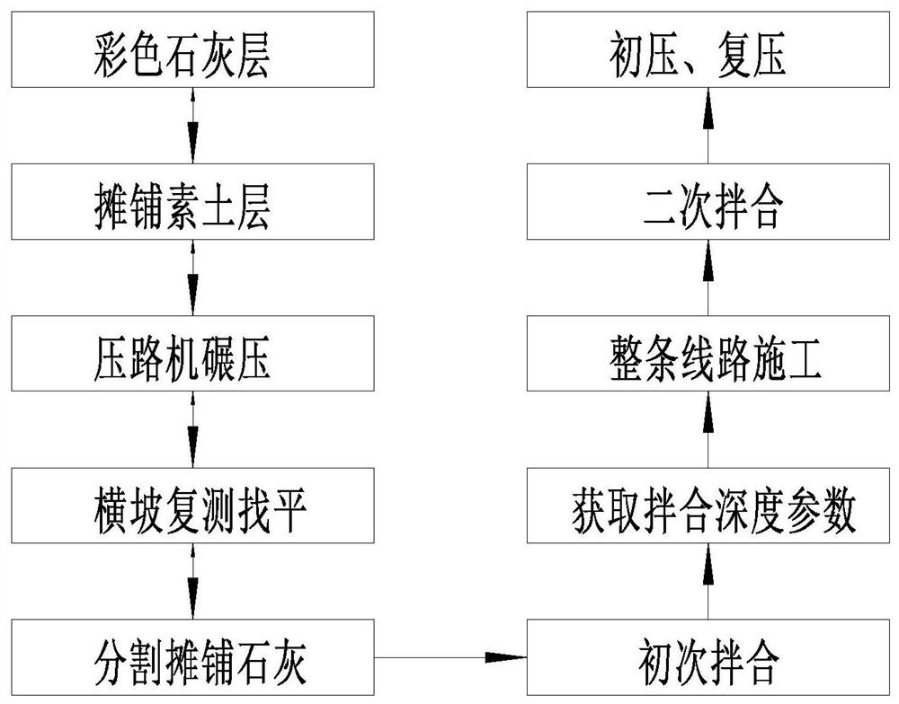
[0037] Such as figure 1 Shown, a kind of lime soil filling construction method is characterized in that, comprises the following steps:

[0038] A1. Spread colored lime with a thickness of 1cm at the starting point of the route construction on the lower bearing layer, with a length of 10-15m;

[0039] A2. Spread the plain soil layer, turn it up to the required moisture content, and the soil clods are less than 15mm, and the plow can be used for construction;

[0040] A3. Rolling with a light roller;

[0041] A4. Cross slope re-measurement and leveling, no wavy surface is allowed;

[0042] A5. Draw the lime grid and spread the lime, and use the scraper 1 to smooth the upper surface of the lime. After the surface is smooth, the lime block cannot exceed 5mm;

[0043] A6. When the road mixer is in place, firstly carry out trial mixing in sections at 10-15m from the starting route;

[0044] A7. According to the drawing, set the thickness of the lime soil layer plus the thicknes...

Embodiment 2

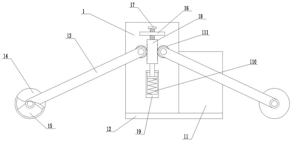
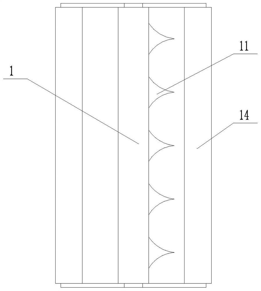
[0053] Such as figure 2 and image 3 As shown, in a further improved solution on the basis of Example 1, the front side of the scraper 1 is integrally connected with a breakaway part 11, and the bottom of the breakaway part 11 is integrally connected with the bottom of the scraper 1 with the same horizontal part 12, Both sides of the breaking part 11 are inwardly concave arc-shaped structures. The path of the demolition part 11 can be leveled first by using the horizontal part 12, and the demolition part 11 will be raised higher than the design height to break the arc-shaped structure and move to both sides and spread evenly, effectively improving the efficiency and construction quality of tiling.

[0054] In the further improved solution in this embodiment, the scraper 1 is rotatably connected with two sets of connecting rods 13 at the front and rear, and the two sets of connecting rods 13 are connected with rolling rollers 14, and one set of rolling wheels is located at th...


PUM


Abstract

The invention discloses a lime soil filling construction method, and belongs to the field of filling construction. According to the invention, secondary mixing is adopted, and lime is spread in grids,so that the on-site lime soil construction depth is effectively guaranteed and the existence of a plain soil interlayer is avoided; meanwhile, a specially-assigned person does not need to follow themachine to carry out digging depth inspection, long-term fatigue operation of the personnel is avoided; besides, by adopting the method, depth errors caused by adopting an expensive road mixer with the automatic depth adjusting function are avoided, and the problem that the mixing operation efficiency cannot be guaranteed due to the fact that the size and the water content of concrete materials cannot be guaranteed by both the person and the machine is solved. Lime is paved by adopting the grid scraping plate, so that the lime is paved more smoothly, two hands of an operator are liberated, andthe operation production efficiency is improved.

Description

technical field [0001] The invention relates to a filling construction method, which is especially suitable for the construction technical scope of lime-flyash soil in road construction. Background technique [0002] Lime soil refers to the combination of lime and plain soil on the lower bearing layer in road construction to strengthen the middle layer of the road surface and roadbed. The difference between lime soil and plain soil filling lies in the control of water content, the uniformity of the mixture, the control of the depth of mixing, and the guarantee of compaction. These factors are the key points of technical operation that directly affect the construction of lime soil. [0003] During normal construction: [0004] 1. The lime soil construction process is: quality inspection of the lower bearing layer - plain soil paving - overturning according to the water content of the plain soil - virtual pressure leveling - cross-cutting - upper digestion of quicklime - spre...

Claims


Application Information

Patent Timeline
IPC IPC(8): E01C3/00E01C3/04
CPCE01C3/00E01C3/04
Inventor 金玲玲李军谢兰敏
Owner CHINA MCC17 GRP
Learn More