Timestamp jitter compensation method and device

A compensation device and compensation method technology, applied in synchronization devices, time division multiplexing systems, electrical components, etc., can solve problems such as time stamp jitter, clock domain conversion error, etc.

Active Publication Date: 2020-10-20
FENGHUO COMM SCI & TECH CO LTD
View PDF6 Cites 1 Cited by
  • Summary
  • Abstract
  • Description
  • Claims
  • Application Information

AI Technical Summary

Problems solved by technology

[0006] In order to solve the problem that the clock domain conversion error of ±8 ns from the time stamp sampling identification signal in the system clock domain or the local clock domain to the time stamp sampling identification signal in t

Method used


Image

  • Timestamp jitter compensation method and device
  • Timestamp jitter compensation method and device
  • Timestamp jitter compensation method and device

Examples


Embodiment Construction

[0041] In order to make the purpose, technical solutions and advantages of the embodiments of the present invention clearer, the technical solutions in the embodiments of the present invention will be clearly described below in conjunction with the accompanying drawings in the embodiments of the present invention. Obviously, the described embodiments are the Some, but not all, embodiments are invented. Based on the embodiments of the present invention, all other embodiments obtained by persons of ordinary skill in the art without making creative efforts belong to the protection scope of the present invention.

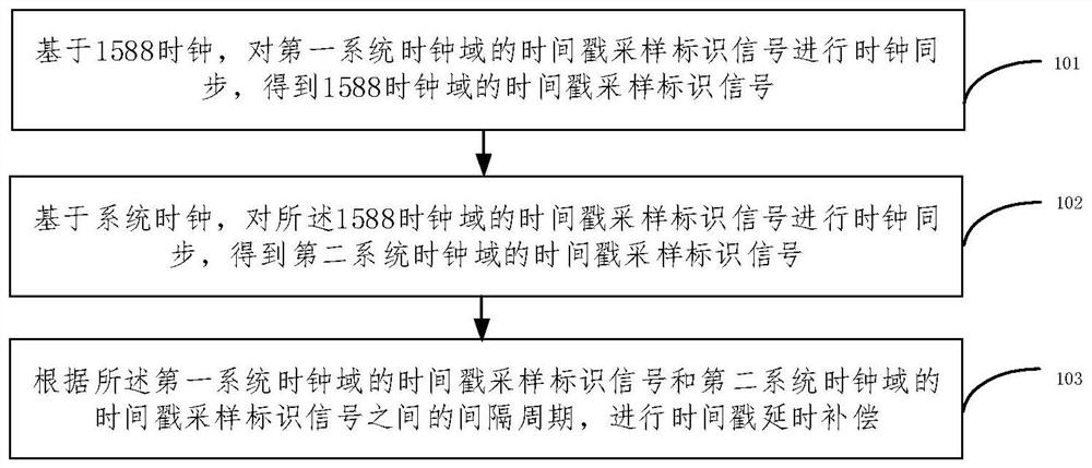
[0042] figure 1 is a schematic flowchart of a time stamp jitter compensation method provided by an embodiment of the present invention, as shown in figure 1 shown, including:

[0043] 101. Based on the 1588 clock, perform clock synchronization on the time stamp sampling identification signal in the first system clock domain to obtain the time stamp sampling identifica...


PUM


Abstract

The embodiment of the invention provides a timestamp jitter compensation method and device, and the method comprises the steps: carrying out the clock synchronization of a timestamp sampling identification signal of a first system clock domain based on a 1588 clock, and obtaining a timestamp sampling identification signal of the 1588 clock domain; performing clock synchronization on the timestampsampling identification signal of the 1588 clock domain based on a system clock to obtain a timestamp sampling identification signal of a second system clock domain; and performing timestamp delay compensation according to the interval period between the timestamp sampling identification signal of the first system clock domain and the timestamp sampling identification signal of the second system clock domain. According to the timestamp jitter compensation method and device provided by the embodiment of the invention, errors caused by synchronization of timestamp sampling identification signalsof a system clock domain are amplified, and then discrimination compensation is carried out, so that the jitter of the timestamp is effectively compensated.

Description

technical field [0001] The present invention relates to the technical field of time synchronization, in particular to a time stamp jitter compensation method and device. Background technique [0002] With the advent of the 5G communication era, 5G communication poses new requirements and challenges for time synchronization technology, and improving the accuracy of time stamps is the key to meeting new requirements. [0003] When processing timestamps, there is a conversion problem from the timestamp sampling identification signal in the system clock domain or the local clock domain to the timestamp sampling identification signal in the 1588 clock domain. For the 125MHz 1588 clock, the clock domain conversion error of the timestamp sampling identification signal is ±8ns, this error will cause the jitter of the time stamp, and then affect the performance of time synchronization. [0004] In the prior art, the time stamp jitter compensation methods include increasing the frequ...

Claims


Application Information

Patent Timeline
IPC IPC(8): H04J3/06H04W56/00
CPCH04J3/0661H04J3/0682H04W56/004
Inventor 冯子钦杨虎林钟永波
Owner FENGHUO COMM SCI & TECH CO LTD
Why Eureka
Try Eureka