
A kind of installation method of roller cleaning device

A technology of cleaning device and installation method, applied in the field of construction machinery, can solve the problems of high abrasion speed, short service life and high replacement frequency of the scraper

Active Publication Date: 2022-01-04
青岛交建集团有限公司
View PDF9 Cites 0 Cited by
  • Summary
  • Abstract
  • Description
  • Claims
  • Application Information

AI Technical Summary

Problems solved by technology

[0004] The embodiment of the present application provides a method for installing the roller cleaning device of a road roller, and the roller cleaning device installed by the installation method solves the problem of the rapid wear, short service life and frequent replacement of the scraper for removing materials in the prior art. Due to high technical problems, the road roller can automatically identify the debris that needs to be cleaned on the pressure roller, and clean up the sticky debris on the surface of the pressure roller in time-sharing to achieve the technical effect of reducing the wear of the shovel plate

Method used


Image

  • A kind of installation method of roller cleaning device
  • A kind of installation method of roller cleaning device
  • A kind of installation method of roller cleaning device

Examples


Embodiment 1

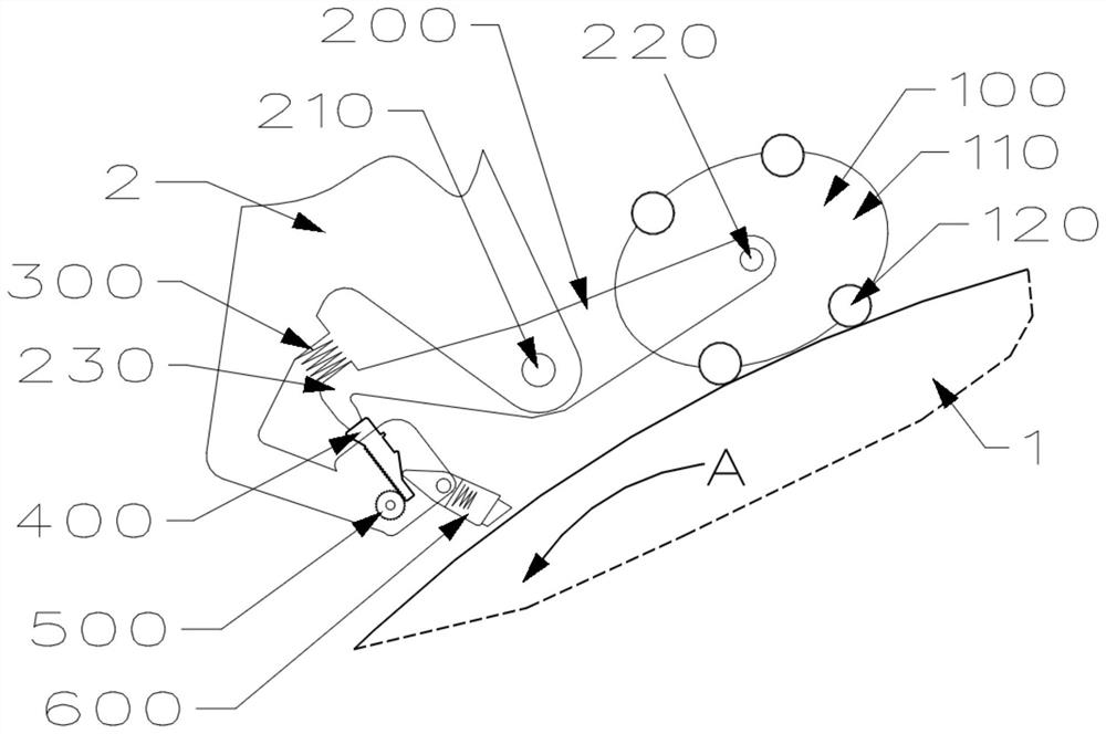
[0085] Such as figure 1 As shown, the supporting roller cleaning device of the present application includes a pilot wheel 100 , a floating lever 200 , a floating lever applying force assembly 300 , a trigger lever 400 , a trigger lever delay reset assembly 500 and a shovel assembly 600 .

[0086] The pilot wheel 100 plays a role in driving the floating lever 20 to rotate around its fulcrum after touching the sticky debris on the pressure roller 1; the pilot wheel 100 includes a pilot wheel main body 110 and a foundation wheel; the main body 110 of the pilot wheel is elliptical, and the midpoint position (center position, center of gravity) of the line connecting the two foci of the ellipse is rotatably and fixedly connected with one end of the floating lever 200; the basic wheel 120 It is rotatably and fixedly connected to the main body 110 of the pilot wheel, and the number of the basic wheels 120 is four, and the four basic wheels 120 are symmetrically arranged in pairs; Th...

Embodiment 2

[0104] Considering that during the operation of the supporting roller cleaning assembly of the application, the wear of the scraping plate 620 (in the process of compensating the wear of the scraping plate 620 by the elastic body 630 extending from the scraping plate) will cause the continuous pressure of the scraping plate on the pressure roller 1 surface. reduce, and then affect the cleaning effect of the shovel plate 620 on sundries (initially the pressure is relatively large, and the cleaning effect is good but the shovel plate 620 wears quickly, and then the pressure gradually decreases, and the cleaning effect becomes worse); for this reason, the present embodiment On the basis of the above-mentioned embodiments, an elastic body elastic force adjusting device 631 is added to reduce the wear speed of the blade 620 at the initial stage of use by adjusting the compressed amount of the elastic body 630 protruding from the blade, while ensuring the cleaning effect. Such as F...

Embodiment 3

[0110] During the actual application of the present application, it was found that the possibility of sticking materials in different areas on the pressure roller 1 is different, which in turn leads to different degrees of wear of the shovel plate 620 in different areas. Sometimes a shovel plate 620 is partially worn too severely and the entire shovel plate 620 needs to be replaced .

[0111] Such as Figure 5 As shown, in view of the above problems, this embodiment divides the entire pressure roller into multiple pressure roller partitions 11 and modularizes the shovel plate 620, and each pressure roller partition 11 corresponds to one shovel plate 620; when it is necessary to replace the shovel plate, only replace the severely worn one. The shovel plate 620.

[0112] Simultaneously, the steps in the second embodiment of the present application are optimized, and step 5 in the optimized embodiment two is:

[0113]The blade casing 610 of the blade assembly 600 is rotatably a...


PUM


Abstract

This application discloses an installation method for a roller cleaning device of a road roller, which is matched with a roller cleaning device of a road roller; the roller cleaning device of a road roller includes a pilot wheel, a floating lever, a floating lever force application component, a trigger lever, and a delayed reset of the trigger lever assembly and scraper assembly; the pilot wheel is rotatably and fixedly connected to one end of the floating lever through sequential steps; the floating lever is rotatably and fixedly connected to the roller frame; the floating lever is installed on the end of the floating lever away from the pilot wheel. The trigger lever delay reset assembly is installed on the frame; the shovel assembly is rotatably and fixedly connected to the roller frame; the trigger lever is installed on the roller frame between the trigger lever delay reset assembly and the shovel assembly; manually rotate and float The lever or pilot wheel simulates the process of cleaning debris, and adjusts the position of the trigger lever according to the floating amount of the simulated floating lever at the end away from the pilot wheel; realizes the installation of the roller cleaning device of the road roller.

Description

technical field [0001] The invention relates to the technical field of engineering machinery, in particular to a method for installing a pressure roller cleaning device of a road roller. Background technique [0002] Road roller, also known as soil compactor, is a kind of equipment for road construction; road roller belongs to the category of road equipment in construction machinery, and is widely used for filling compaction in large-scale engineering projects such as high-grade highways, railways, airport runways, dams, and stadiums. For practical operation, it can roll sandy, semi-cohesive and cohesive soil, roadbed stabilized soil and asphalt concrete pavement layer. With the gravity of the machine itself, the road roller is suitable for various compaction operations, so that the rolled layer can be permanently deformed and compacted. [0003] When the road roller is rolling on the soil layer, the surface of the roller will adhere to soil, clay and other materials. If th...

Claims


Application Information

Patent Timeline
Patent Type & Authority Patents(China)
IPC IPC(8): B23P21/00E01C19/23
CPCB23P21/004B23P21/00E01C19/238
Inventor 李田芳
Owner 青岛交建集团有限公司
Learn More