Jelly cup blowing dropping device of jelly production line

A technology for jelly cups and production lines, which is used in packaging, transportation and packaging, conveyor objects, etc., can solve the problems of time-consuming and laborious, complicated installation structure, and difficult to clean up hidden dirt.

Pending Publication Date: 2020-10-23
LUOHE LIANTAI FOOD
View PDF0 Cites 0 Cited by
  • Summary
  • Abstract
  • Description
  • Claims
  • Application Information

AI Technical Summary

Problems solved by technology

[0003] For this reason, the company adopts a jelly cup jacking and dropping device in the jelly production line, which uses a motor to drive the driving shaft to rotate, and the driving sprocket drives the passive sprocket to rotate through the chain. The jelly cup shelf is placed on the two chains. , during the movement of the chain, the jelly cup is transferred from front to back. When it is transferred to the rear end of the rack, the jelly cup placement frame rotates around the passive sprocket to insert the jacking rod into the jacking hole of the jelly cup to jack the jelly cup and turn it over , the jelly cup will fall easily from the jelly cup placement mouth under its own gravity. When the jacking rod is inserted into the jelly cup jacking hole to jack the jelly cup, there will be a phenomenon of pinching the jelly cup, resulting in waste jelly, jelly cup The installation structure of the jacking and dropping device is complicated, and the residual jelly is easy to mold and deteriorate for a long time. When cleaning, the outer part template needs to be removed to clean it. The hidden dirt inside is difficult to clean, which is time-consuming and laborious.

Method used


Image

  • Jelly cup blowing dropping device of jelly production line
  • Jelly cup blowing dropping device of jelly production line
  • Jelly cup blowing dropping device of jelly production line

Examples


Embodiment Construction

[0018] The present invention will be further described below in conjunction with the accompanying drawings.

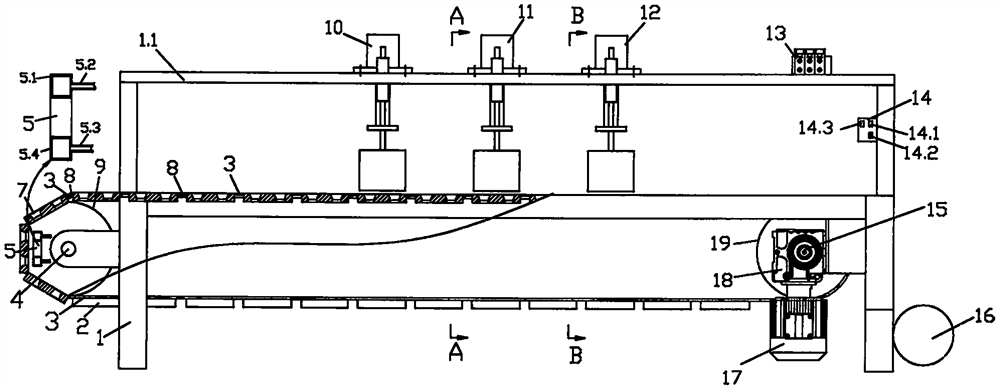
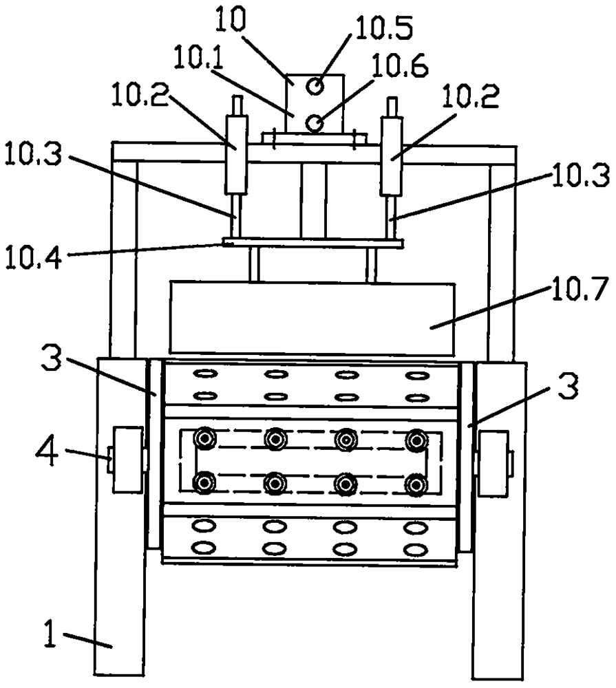
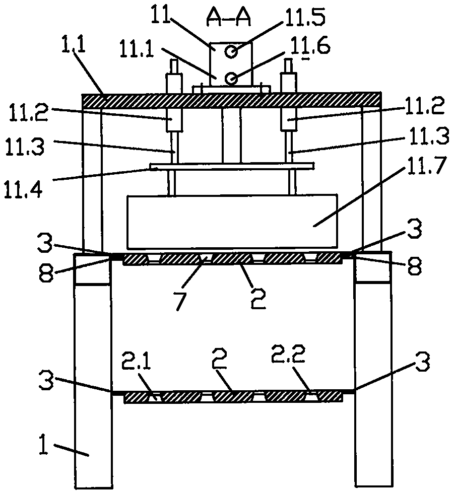
[0019] like Figure 1-Figure 6As shown, the jelly cup blowing and dropping device of the jelly production line includes a frame 1, and the front end of the frame 1 is fixedly connected to a reducer 18, and the reducer 18 is respectively connected to the motor 17 and the drive shaft 15, and the drive shaft 15 is fixedly connected to the drive shaft. Sprocket 19; the rear end of the frame 1 rotates to connect the driven shaft 4, and the driven shaft 4 is fixedly connected to the driven sprocket 9; the driving sprocket 19 and the driven sprocket 9 are connected by a chain 3 transmission; the frame 1 is provided with a chain Supporting plate 8, chain supporting plate 8 supporting chains; chain 3 is provided with jelly cup placement rack 2, jelly cup placement rack 2 is provided with jelly cup placement hole 2.1, jelly cup placement hole 2.1 places jelly cup 7, jelly cup pl...


PUM


Abstract

The invention discloses a jelly cup blowing dropping device of a jelly production line. A blowing device is arranged at the rear end of a rack. The blowing device comprises a rectangular annular air pipe fixedly connected to the rack. Air outlet holes are distributed in the front lateral side of the rectangular annular air pipe in an array mode and are formed in the rear side of a jelly cup blowing hole of a jelly cup placing rack moving to a vertical position. The rear lateral side of the rectangular annular air pipe communicates with an air pipe upper air inlet pipe and an air pipe lower airinlet pipe. A valve seat upper air hole is in air connection with an air pipe upper air inlet pipe. A valve seat lower air hole is in air connection with an air pipe lower air inlet pipe. A jelly cupis prevented from being clamped in a jelly cup placing hole under the action of high-pressure waste gas flow, and drops from the jelly cup placing hole under the action of self-gravity. The problem that the jelly cup cannot drop normally is effectively solved, cup clamping is avoided, the dropping efficiency is improved, and meanwhile, the jelly cup is prevented from being clamped and damaged, the yield is improved, cleanness and sanitation are achieved, and waste gas is utilized to blow the jelly cup, so that the energy is saved, and the cost is reduced.

Description

technical field [0001] The invention belongs to the field of food machinery, and in particular relates to a jelly cup blowing and dropping device for a jelly production line. Background technique [0002] Our company is mainly engaged in food processing and production, among which jelly is the main product of our company. When injecting the jelly liquid into the jelly cup, first place the jelly cup on the jelly cup placement plate, and then inject the liquid into the jelly cup. When the liquid cools, it will solidify. Therefore, when injecting the liquid, the liquid must have Only at a certain temperature can it have fluidity. After the material liquid is injected, the film coating work is carried out, and then the film cutting work is carried out. During the whole process, the jelly cup placement plate is placed on the two chains, and the jelly is transmitted forward during the movement of the chains. When conveyed to the end of the chain, the jelly cup placement plate wi...

Claims


Application Information

Patent Timeline
Patent Type & Authority Applications(China)
IPC IPC(8): B65B61/28B65G47/34
CPCB65B61/28B65G47/34
Inventor 赵向党赵晓阳宋志永罗改丽杨自平薛童赵铁良冯建立
Owner LUOHE LIANTAI FOOD
Why Eureka
Try Eureka