Angle adjusting structure of drawer panel

An angle adjustment structure and angle adjustment technology, applied in garbage collection, home appliances, applications, etc., can solve problems such as panel tilting up and down, gaps in cabinets, affecting the appearance of drawers, etc.

Pending Publication Date: 2020-10-23
GUANGDONG DTC HARDWARE PRECISION MFG CO LTD
View PDF2 Cites 0 Cited by
  • Summary
  • Abstract
  • Description
  • Claims
  • Application Information

AI Technical Summary

Problems solved by technology

It is said that the drawer of the above-mentioned structure is used to support the trash can body, and it is convenient to take out and put in the trash can body. When installing, the entire box body can be embedded in the wall table, saving space, and the trash can body can be easily taken out and put in. Putting it in, the trash can body can be prevented from dumping under the fixing of the bucket ring; however, in orde

Method used


Image

  • Angle adjusting structure of drawer panel
  • Angle adjusting structure of drawer panel
  • Angle adjusting structure of drawer panel

Examples


no. 1 example

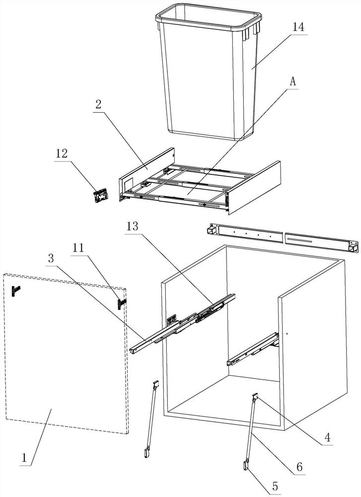
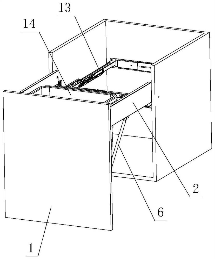
[0027] see Figure 1-Figure 6 , the angle adjustment structure of the drawer panel, comprising a panel 1, a side panel 2 and a slide rail assembly, characterized in that: the slide rail assembly at least includes a moving slide rail 3, the side panel 2 is detachably arranged on the moving slide rail 3, and the panel 1. It is detachably installed on the side plate 2; wherein, the side plate 2 or the moving slide rail 3 is provided with a first connecting piece 4, and the panel 1 is provided with a second connecting piece 5, and the first connecting piece 4 is connected with the second A connecting rod 6 is arranged between the parts 5, an adjusting member is arranged between the connecting rod 6 and the first connecting member 4 and / or the second connecting member 5, and the connecting rod 6 moves between the first connecting member 4 and the second connecting member 5 through the adjustment of the adjusting member. / or on the second connecting member 5, and when in motion, the...

no. 2 example

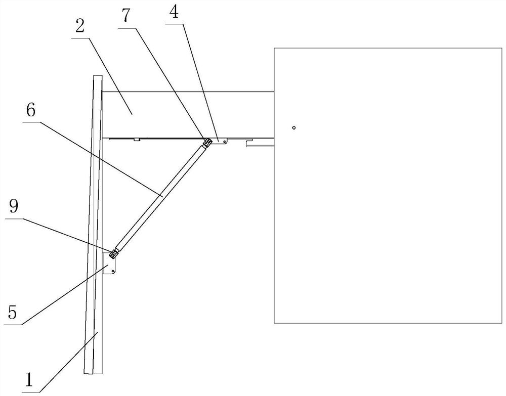
[0043] see Figure 7 , The angle adjustment structure of the drawer panel is different from the first embodiment in that: the first connecting piece 4 is arranged on the moving slide rail 3 .

[0044] The connecting rod 6 moves on the first connecting member 4 and / or the second connecting member 5 through the adjustment of the adjusting member, and drives the panel 1 to tilt relative to the sliding rail 3 when in motion, so as to realize the angle adjustment of the panel 1 .

[0045] The connection between the moving slide rail 3 and the first connecting member 4 forms a second action point.

[0046] Specifically, the first connecting member 4 is fixedly arranged on the movable sliding rail 3 and forms a second action point with each other.

[0047] Use a tool or manual action on the connecting rod 6, and drive the two ends of the connecting rod 6 to be threaded and rotate between the first adjusting member 7 and the second adjusting member 9, and the connecting rod 6 will dr...


PUM


Abstract

The invention relates to an angle adjusting structure of a drawer panel. The angle adjusting structure comprises a panel, a side plate and a sliding rail assembly, and is characterized in that the sliding rail assembly at least comprises a movable sliding rail, the side plate is detachably arranged on the movable sliding rail, and the panel is detachably arranged on the side plate; a first connecting piece is arranged on the side plate or the movable sliding rail, a second connecting piece is arranged on the panel, a connecting rod is arranged between the first connecting piece and the secondconnecting piece, and an adjusting piece is arranged between the connecting rod and the first connecting piece and/or the second connecting piece; the connecting rod moves on the first connecting piece and/or the second connecting piece through adjustment of the adjusting piece and drives the panel to obliquely move relative to the side plate or the movable sliding rail in the moving process, thereby realizing the angle adjustment of the panel. The upper position and the lower position of the panel can be attached to a cabinet body better when the panel is closed, and the problems that in theprior art, the height size of the panel is quite large, or the manufacturing specification is inconsistent, or dislocation occurs during installation, so that a gap is formed between the panel and thecabinet body when the panel is closed, and appearance regularity is affected are solved.

Description

technical field [0001] The invention relates to an angle adjustment structure of a drawer panel. Background technique [0002] The Chinese patent literature number is CN204624410U on September 9, 2015, which discloses a drawer-type trash can, which includes a panel, the panel includes an inner surface and an outer surface, and the inner surface of the panel is fixed with a trash can bucket. The drawer of the body, the panel above the drawer is fixed with a bucket ring, the barrel body of the garbage can is sleeved in the bucket ring, a handle is arranged on the outer surface of the panel, and an outer frame is arranged around the panel . It is said that the drawer of the above-mentioned structure is used to support the trash can body, and it is convenient to take out and put in the trash can body. When installing, the entire box body can be embedded in the wall table, saving space, and the trash can body can be easily taken out and put in. Putting it in, the trash can body...

Claims


Application Information

Patent Timeline
IPC IPC(8): B65F1/14
CPCB65F1/14
Inventor 伍志勇
Owner GUANGDONG DTC HARDWARE PRECISION MFG CO LTD
Why Eureka
Try Eureka