Automatic valve device applied to washing and dewatering equipment

A technology for washing water and valves, which can be used in textile material equipment configuration, textile material processing, textile and paper making, etc. It can solve the problems of damaged laundry and inability to soak for a long time

Inactive Publication Date: 2020-10-23
常瑛超
View PDF0 Cites 0 Cited by
  • Summary
  • Abstract
  • Description
  • Claims
  • Application Information

AI Technical Summary

Problems solved by technology

[0002] A valve is a device that controls the flow of liquid inside a pipeline, and now most of the valves basically stay in the state of "stop flow" and "start flow" for liquid control, so most of the related equipment can only be kept Receive the water flow or stop the water flow infusion, and for the washing and dewatering equipment, some washings are more expensive and cannot be soaked in the water flow for a long time, and the washings need to be completely wet to wash effectively. Generally, the water flow is fluid and intrusive, and a small water flow can wet a large area of ​​laundry. However, due to the characteristics of valve control, in order to improve the efficiency and the range of wetting, it is necessary to make the laundry wet in a large area. Soaking in the liquid will damage part of the laundry. For this reason, we propose an automatic valve device applied to the washing water equipment

Method used


Image

  • Automatic valve device applied to washing and dewatering equipment
  • Automatic valve device applied to washing and dewatering equipment
  • Automatic valve device applied to washing and dewatering equipment

Examples


Embodiment Construction

[0027] The following will clearly and completely describe the technical solutions in the embodiments of the present invention with reference to the accompanying drawings in the embodiments of the present invention. Obviously, the described embodiments are only some, not all, embodiments of the present invention. Based on the embodiments of the present invention, all other embodiments obtained by persons of ordinary skill in the art without making creative efforts belong to the protection scope of the present invention.

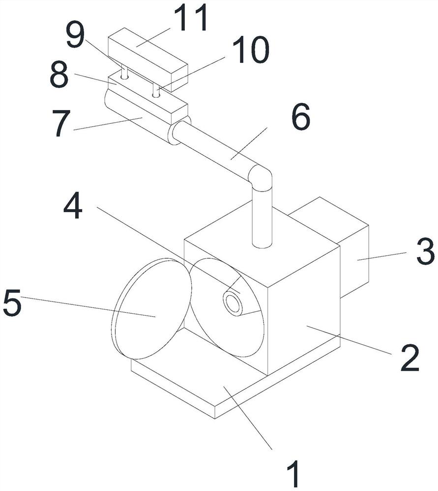
[0028] see Figure 1-Figure 5, the present invention provides a technical solution: an automatic valve device applied to elution water equipment, including a base 1, the base 1 is in the shape of a rectangular plate, and the right side of the top wall of the base 1 is fixedly installed There is an equipment box 2, the equipment box 2 is a rectangular box shape, the inside of the equipment box 2 is circular and hollow, and the hollow area inside the equipment b...


PUM


Abstract

The invention discloses an automatic valve device applied to washing and dewatering equipment, and relates to the technical field of washing and dewatering equipment valves. The automatic valve devicecomprises a base, wherein the base is in a rectangular plate shape, an equipment box is fixedly arranged on the right side of the top wall surface of the base, and the equipment box is in a rectangular box shape. According to the automatic valve device applied to the washing and dewatering equipment, an auxiliary control motor is started, an auxiliary limiting shaft is used for controlling a regulating area in an adjusting box to operate, a slow limiting shaft, a slow driving gear and a driving gear are matched to enable a slow gate plate to rotate slowly, so that water flow enters the frontside area of the slow gate plate; and a driving limiting shaft, a driving regulating gear and an auxiliary driving gear are matched to enable a gate discharging plate to rotate quickly, so that the water flow in a main sleeve is intermittently transmitted into an auxiliary roller, and as a result, washings are intermittently and fully wetted, and the effect of fully wetting the washings by adopting less water flow is achieved.

Description

technical field [0001] The invention relates to the technical field of valves for elution water equipment, in particular to an automatic valve device applied to elution water equipment. Background technique [0002] A valve is a device that controls the flow of liquid inside a pipeline, and now most of the valves basically stay in the state of "stop flow" and "start flow" for the control of liquid, so most of the related equipment can only be kept Receive the water flow or stop the water flow, and for the washing and dewatering equipment, some washings are more expensive and cannot be soaked in the water flow for a long time, and the washings need to be completely wet during washing to be able to wash effectively. Usually, the water flow is fluid and intrusive, and a small water flow can wet a large area of ​​laundry. However, due to the characteristics of valve control, in order to improve the efficiency and the range of wetting, it is necessary to make the laundry wet in a...

Claims


Application Information

Patent Timeline
IPC IPC(8): D06B3/10D06B23/20
CPCD06B3/10D06B23/20
Inventor 常瑛超
Owner 常瑛超
Why Eureka
Try Eureka