Dry-wet separation-type preshrinking device

A dry and wet separation and pre-shrinking technology, which is applied in the processing of textile material equipment configuration, heating/cooling fabric, textile material processing, etc., can solve the problems of affecting the service life of components, poor pre-shrinking effect, and short service life of devices To achieve the effect of improving fabric quality, improving service life, and good moisturizing effect

Inactive Publication Date: 2018-09-28
湖州织里凯狄酷娃服饰有限公司
View PDF0 Cites 2 Cited by
  • Summary
  • Abstract
  • Description
  • Claims
  • Application Information

AI Technical Summary

Problems solved by technology

[0002] The fabric pre-shrinking device is an indispensable finishing equipment in the modern garment production process of textile machinery. After the fabric is pre-shrunk, the shrinkage rate can be stabilized, and the quality and dimensional stability of the fabric can be further improved. The existing fabric pre-shrinking generally uses steam Steam pre-shrinking is designed according to the principle of fiber heat shrinkage; however, the existing fabric pre-shrinking device is often used to wet, pre-shrink, and dry fabrics in the same box, and a spraying mechanism is set above the hot roller of the pre-shrinking mechanism. Make the fabric wet, this design makes the whole box in a humid environment, which greatly affects the service life of each internal component, and the fabric moistening effect is also poor, and the fabric is often not wet evenly, resulting in poor pre-shrinking effect
Therefore, the existing pre-shrinking device has the problems that the fabric cannot be fully wetted, the pre-shrinking effect of the fabric is poor, and the service life of the device is short.

Method used


Image

  • Dry-wet separation-type preshrinking device
  • Dry-wet separation-type preshrinking device
  • Dry-wet separation-type preshrinking device

Examples


Embodiment

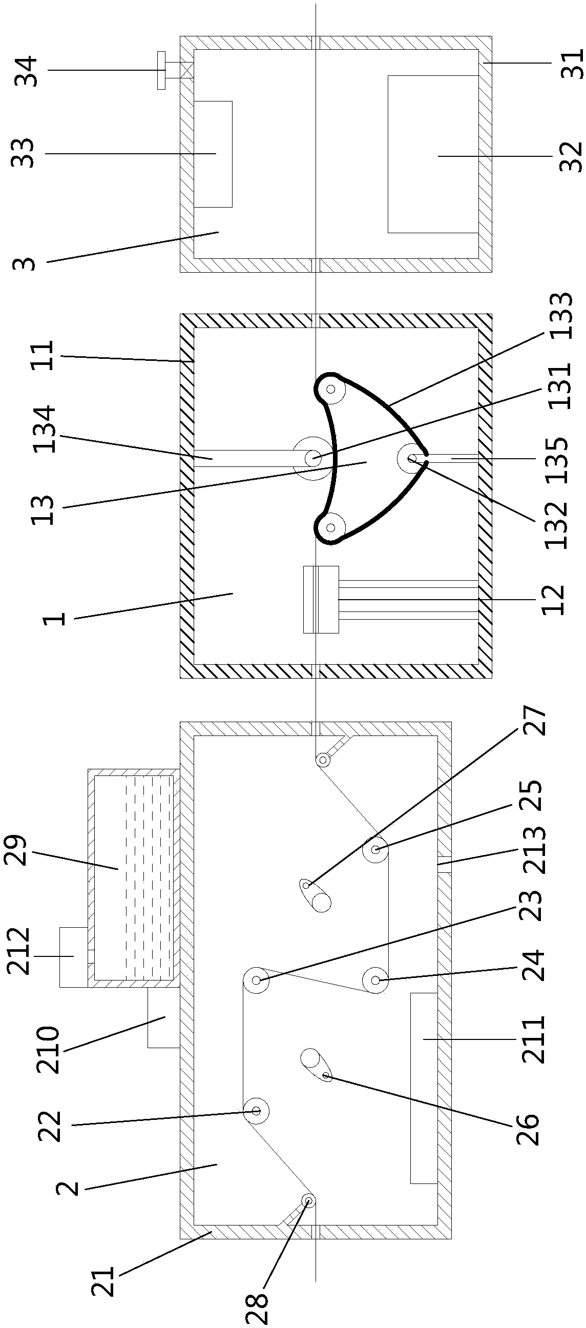
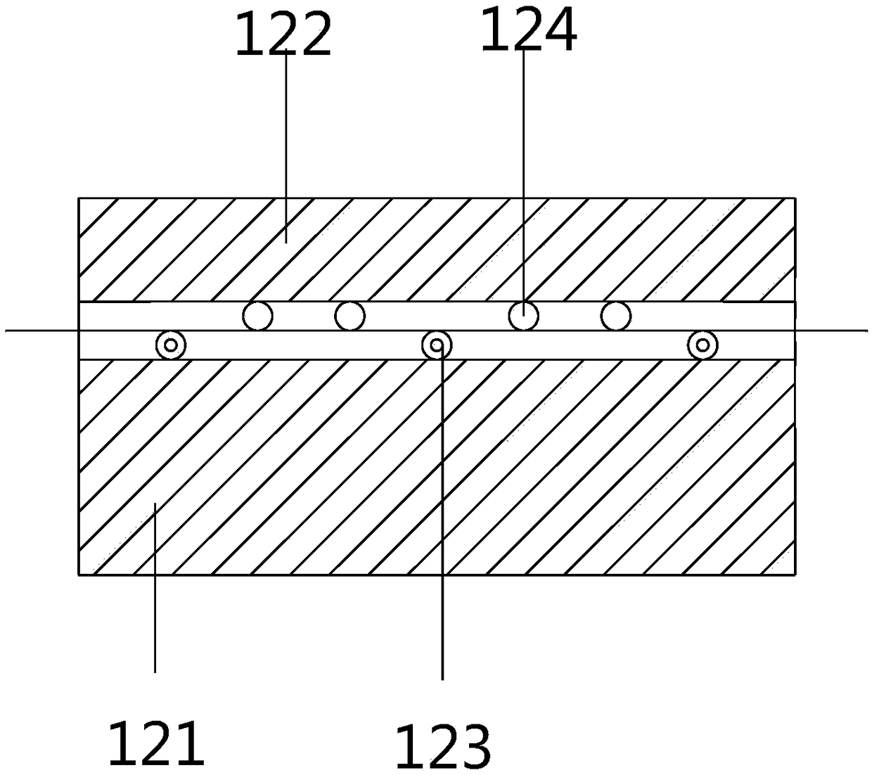
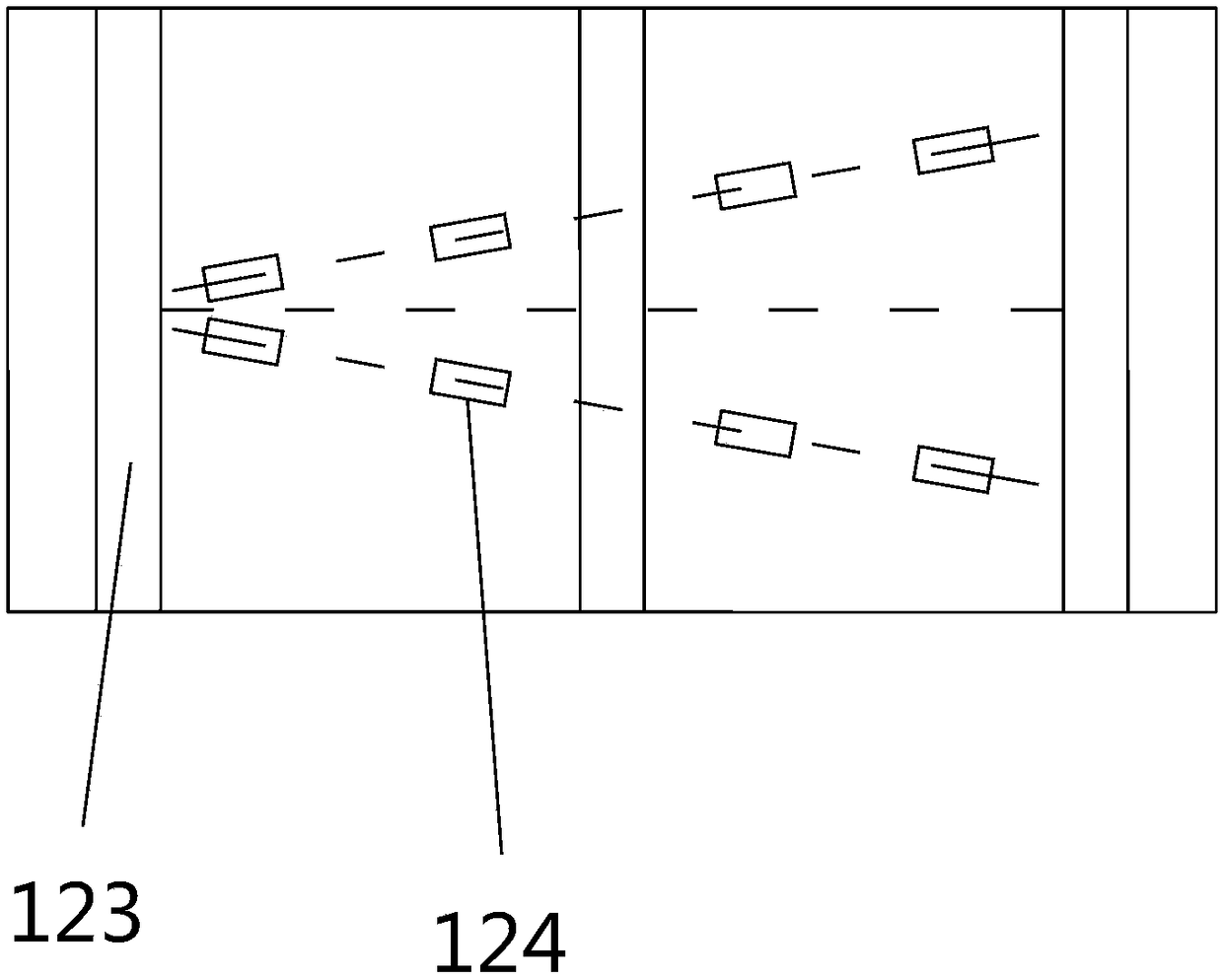
[0022] Embodiment: a dry-wet separation pre-shrinking device, the structure is as Figure 1 to Figure 3 As shown, it includes a pre-shrinking mechanism 1, and the two sides of the pre-shrinking mechanism 1 are respectively provided with a moisture supply mechanism 2 and a drying mechanism 3; The first drive roller 22, the second drive roller 23, the third drive roller 24 and the fourth drive roller 25 arranged in a misplaced position, the plane formed by the second drive roller 23 and the third drive roller 24 is perpendicular to the bottom surface of the humidification box 21, The front and rear sides of the plane where the second drive roller 23 and the third drive roller 24 are located are respectively provided with a first steam spray nozzle 26 and a second steam spray nozzle 27, and guide rollers 28 are provided on both sides of the feed and discharge inside the wet box body 21; The pre-shrinking mechanism 1 includes a pre-shrinking box 11, and the pre-shrinking box 11 is...


PUM


Abstract

The invention discloses a dry-wet separation-type preshrinking device. The device includes a preshrinking mechanism, and a wetting mechanism and a drying mechanism are arranged on the two sides of thepreshrinking mechanism respectively; the wetting mechanism includes a wetting box body, and the internal space of the wetting box body is provided with a first transmission roller, a second transmission roller, a third transmission roller and a fourth transmission roller which are arrayed staggeredly; a first vapor sprayer and a second vapor sprayer are arranged on the front and rear sides of theplane where the second transmission roller and the third transmission roller are positioned. The preshrinking mechanism includes a preshrinking box body, and the preshrinking box body is internally provided with a fabric flattening device and a preshrinking mechanism body; the fabric flattening device comprises a lower shell body and an upper shell body, a fifth transmission roller is arranged inthe lower shell body, multiple groups of flattening wheels are arranged in the upper shell body, and the axial directions of the flattening wheels are spatially intersected with the fifth transmission roller. The device has the advantages that fabric can be thoroughly wetted, the preshrinking effect of the fabric is great, and the service life of the device is long.

Description

technical field [0001] The invention relates to a pre-shrinking device, in particular to a dry-wet separation type pre-shrinking device. Background technique [0002] The fabric pre-shrinking device is an indispensable finishing equipment in the modern garment production process of textile machinery. After the fabric is pre-shrunk, the shrinkage rate can be stabilized, and the quality and dimensional stability of the fabric can be further improved. The existing fabric pre-shrinking generally uses steam Steam pre-shrinking is designed according to the principle of fiber heat shrinkage; however, the existing fabric pre-shrinking device is often used to wet, pre-shrink, and dry fabrics in the same box, and a spraying mechanism is set above the hot roller of the pre-shrinking mechanism. Wetting the fabric, this design makes the whole box in a humid environment, which greatly affects the service life of each internal component, and the fabric is also poorly moistened, and the fab...

Claims


Application Information

Patent Timeline
Patent Type & Authority Applications(China)
IPC IPC(8): D06B1/02D06C7/00D06B23/20D06B15/00
CPCD06B1/02D06B15/00D06B23/20D06C7/00
Inventor 汪玉华
Owner 湖州织里凯狄酷娃服饰有限公司
Why Eureka
Try Eureka