
Ventilation and humidification system, air conditioner system, and air conditioner system control method

A technology of humidification system and air conditioning system, which is applied in the direction of air conditioning system, ventilation system, heating and ventilation control system, etc. It can solve the problems of large resistance and achieve the effect of improving the efficiency of fresh air

Pending Publication Date: 2020-10-23
GREE ELECTRIC APPLIANCES INC +1
View PDF0 Cites 5 Cited by
  • Summary
  • Abstract
  • Description
  • Claims
  • Application Information

AI Technical Summary

Problems solved by technology

[0004] The main purpose of the present invention is to provide a ventilation and humidification system, an air-conditioning system and an air-conditioning system control method to solve the problem that the wet film has a large resistance to outdoor fresh air in the prior art

Method used


Image

  • Ventilation and humidification system, air conditioner system, and air conditioner system control method
  • Ventilation and humidification system, air conditioner system, and air conditioner system control method
  • Ventilation and humidification system, air conditioner system, and air conditioner system control method

Examples


Embodiment Construction

[0032] It should be noted that, in the case of no conflict, the embodiments in the present application and the features in the embodiments can be combined with each other. The present invention will be described in detail below with reference to the accompanying drawings and examples.

[0033] It should be noted that, unless otherwise specified, all technical and scientific terms used in this application have the same meaning as commonly understood by those of ordinary skill in the art to which this application belongs.

[0034] In the present invention, in the absence of a contrary statement, the used orientation words such as "up and down" usually refer to the direction shown in the drawings, or refer to the vertical, vertical or gravity direction Similarly, for the convenience of understanding and description, "left and right" usually refer to the left and right shown in the drawings; The words are not used to limit the invention.

[0035]In order to solve the problem in ...


PUM


Abstract

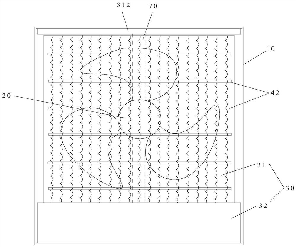
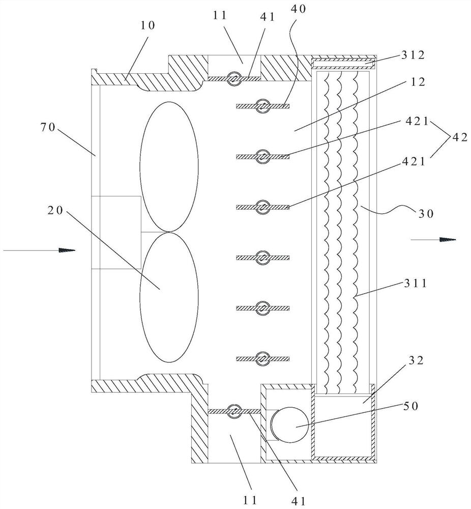
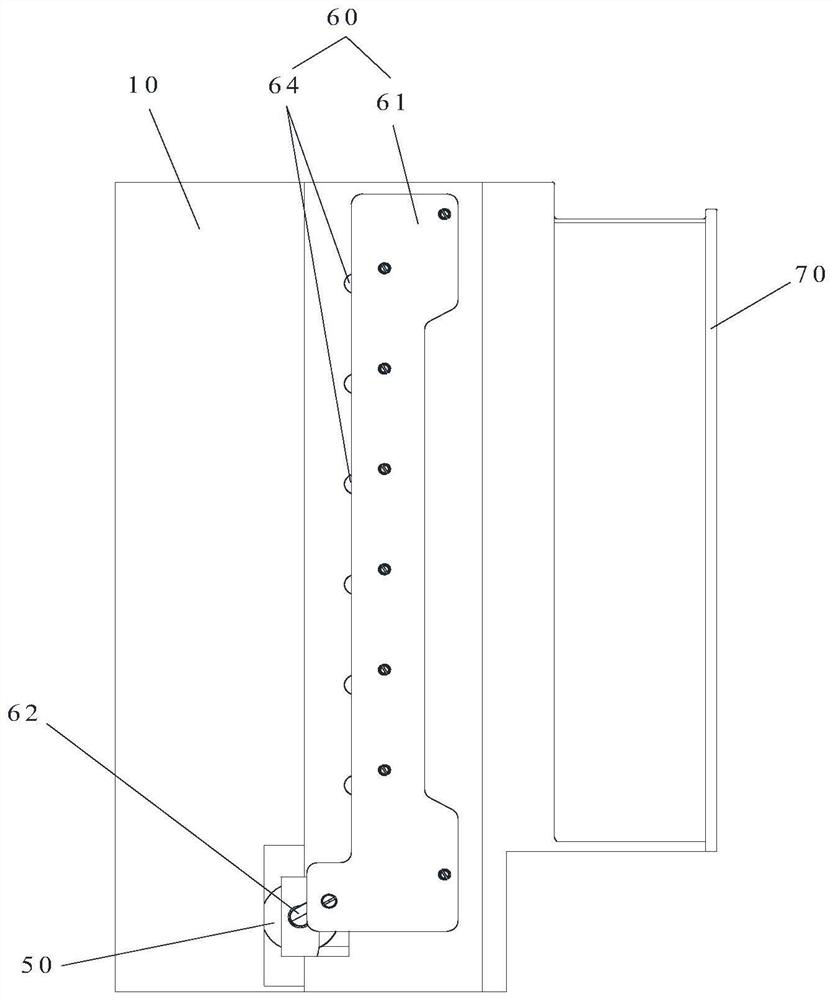
The invention provides a ventilation and humidification system, an air conditioner system, and an air conditioner system control method. The ventilation and humidification system comprises a ventilation and humidification device and a shielding structure. The ventilation and humidification device comprises a shell, a fan and a humidification assembly. The shell is provided with a first air outletand a second air outlet. The fan is arranged in the shell. An air inlet of the fan communicates with the outdoors. The humidification assembly is arranged at the second air outlet and is opposite to an exhaust port of the fan so as to humidify outdoor fresh air discharged from the exhaust port. The shielding structure has a first shielding state for shielding the first air outlet and a second shielding state for shielding the second air outlet. When the shielding structure is in the first shielding state, the outdoor fresh air goes into the fan and is humidified through the humidification assembly and blown to the indoors. When the shielding structure is in the second shielding state, the outdoor fresh air goes into the fan and is blown to the indoors through the first air outlet. Throughthe ventilation and humidification system, the problem that the resistance of a wet film to the outdoor fresh air is large in the prior art is effectively solved.

Description

technical field [0001] The invention relates to the technical field of air conditioning, in particular to a ventilation and humidification system, an air conditioning system, and a control method for the air conditioning system. Background technique [0002] At present, in the cooling process of the air conditioning system, the cooling is performed only by starting the compressor, resulting in high energy consumption of the air conditioning system. [0003] In order to solve the above problems, in the prior art, the outdoor fresh air is humidified by setting a wet film at the fresh air inlet, so as to reduce the indoor heat load. However, in the process of fresh air intake, due to the large resistance of the wet film during ventilation, and the water remaining on the wet film after humidifying the wet film will increase the indoor humidity load during ventilation and affect the efficiency of fresh air intake. Contents of the invention [0004] The main purpose of the pres...

Claims


Application Information

Patent Timeline
Patent Type & Authority Applications(China)
IPC IPC(8): F24F1/0003F24F1/0035F24F1/0087F24F1/42F24F7/007F24F11/64F24F11/72F24F11/86F24F11/88F24F13/22F24F110/10F24F110/12F24F110/20F24F110/22
CPCF24F1/0003F24F1/0035F24F1/0087F24F1/42F24F7/007F24F11/64F24F11/72F24F11/86F24F11/88F24F13/22F24F2110/10F24F2110/12F24F2110/20F24F2110/22F24F2013/228
Inventor 袁琪石文星王宝龙叶强蔚邵莹河毕增利
Owner GREE ELECTRIC APPLIANCES INC
Learn More