Ventilation and humidification device, air conditioner system and air conditioner system control method

A technology of humidification device and air conditioning system, which is applied in the direction of air conditioning system, ventilation system, heating and ventilation control system, etc., and can solve problems such as large resistance

Pending Publication Date: 2020-10-23
GREE ELECTRIC APPLIANCES INC
View PDF0 Cites 2 Cited by
  • Summary
  • Abstract
  • Description
  • Claims
  • Application Information

AI Technical Summary

Problems solved by technology

[0004] The main purpose of the present invention is to provide a ventilation and humidification device, an air-conditioning system and an

Method used


Image

  • Ventilation and humidification device, air conditioner system and air conditioner system control method
  • Ventilation and humidification device, air conditioner system and air conditioner system control method
  • Ventilation and humidification device, air conditioner system and air conditioner system control method

Examples


Embodiment 1

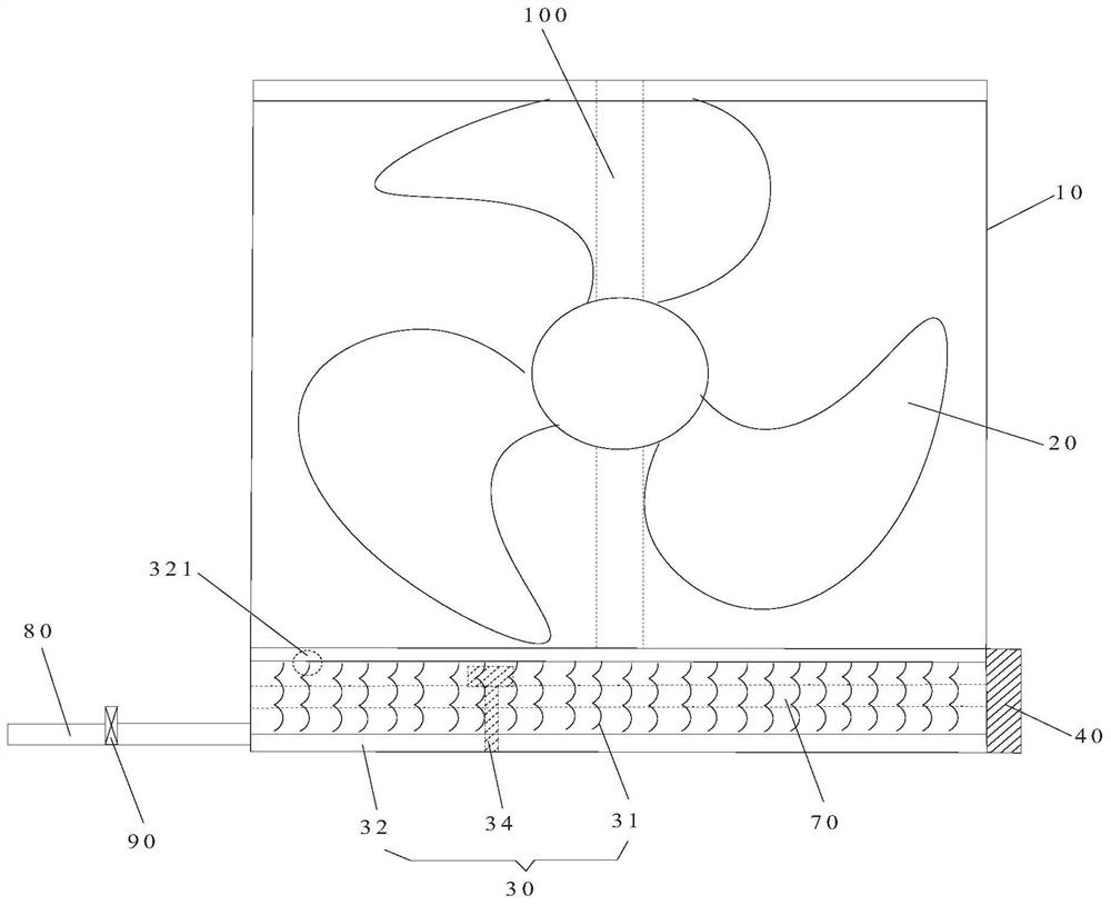
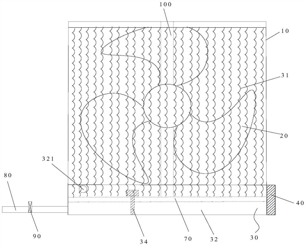
[0036] Such as Figure 1 to Figure 3 As shown, the ventilation and humidification device includes a casing 10 , a fan 20 and a humidification assembly 30 . The casing 10 has an air outlet 11 . The fan 20 is arranged in the casing 10, and the air inlet of the fan 20 communicates with the outside. The humidifying component 30 is arranged opposite to the air outlet of the fan 20 , and outdoor fresh air enters into the fan 20 through the air inlet, and is humidified by the humidifying component 30 before blowing into the room. Wherein, the humidifying assembly 30 includes a humidifying structure 31 movably arranged at the air outlet 11 , and the humidifying structure 31 has a humidifying state of blocking the air outlet 11 and an avoidance state of avoiding at least part of the air outlet 11 .

[0037]Applying the technical solution of the present invention, the humidifying structure 31 has a humidification state of blocking the air outlet 11 and an avoidance state of avoiding a...

Embodiment 2

[0072] The difference between the ventilating and humidifying device in the second embodiment and the first embodiment is that the structure of the ventilating and humidifying device is different.

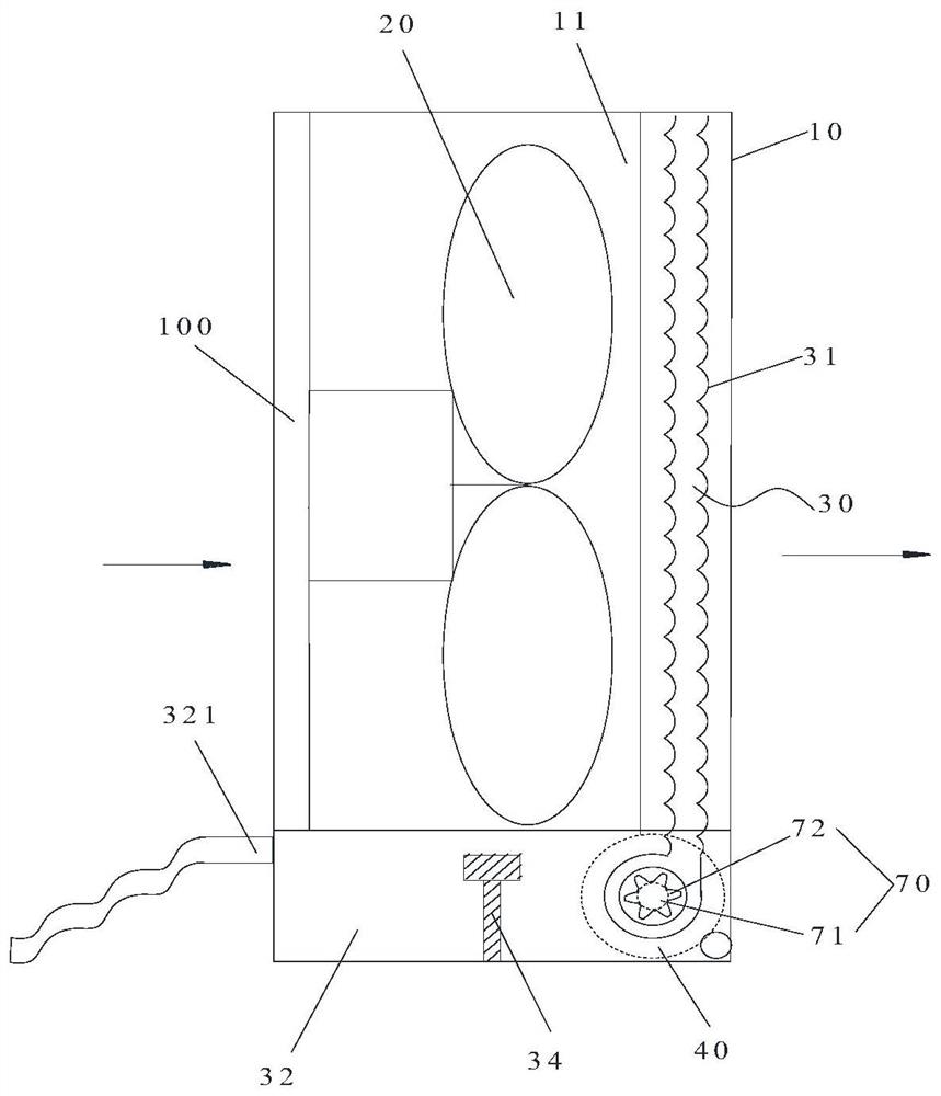
[0073] Such as Figure 4 to Figure 7 As shown, the humidification assembly 30 also includes a spray structure 33 and a liquid storage structure 32 . The spray structure 33 is arranged opposite to at least part of the wet film, so that the liquid sprayed by the spray structure 33 falls on the wet film. Wherein, the spray structure 33 is connected with the liquid supply device. The liquid storage structure 32 is located below the wet film for receiving the liquid sprayed from the spray structure 33 . In this way, the ventilation and humidification device directly uses the temperature difference and humidity difference to save energy, and reduce the indoor sensible heat load while meeting the indoor requirements. After the fan 20 is started, the outdoor fresh air is blown to the we...

Embodiment 3

[0085] The difference between the ventilation and humidification device in the third embodiment and the second embodiment is that the structure of the ventilation and humidification device is different.

[0086] In this embodiment, the ventilation and humidification device further includes an annular slide rail. One end of the fixed structure is fixedly arranged on the annular slide rail, and the other end of the fixed structure extends radially along the annular slide rail. One end of the rotating structure is slidably arranged on the annular slide rail, and the other end of the rotating structure extends radially along the annular slide rail. Wherein, the central axis of the annular slide rail is coaxially arranged with the pivot axis. In this way, both the fixed structure and the rotating structure are arranged on the annular slide rail, so that the first side and the second side of the wet film can be butted, which further improves the humidification efficiency of the wet...


PUM


Abstract

The invention provides a ventilation and humidification device, an air conditioner system and an air conditioner system control method. The ventilation and humidification device comprises a shell, a fan and a humidification assembly, wherein the shell is provided with an air outlet; the fan is arranged in the shell, and an air inlet of the fan communicates with the outdoors; the humidification assembly is opposite to an exhaust port of the fan; outdoor fresh air goes into the fan through the air inlet and is humidified through the humidification assembly and then blown into a room; the humidification assembly comprises a humidification structure movably arranged at the air outlet; and the humidification structure has a humidification state for closing the air outlet and an avoiding state for avoiding at least part of the air outlet. Through the ventilation and humidification device, the problem that a wet film has large resistance to outdoor fresh air in the prior art is effectively solved.

Description

technical field [0001] The invention relates to the technical field of air-conditioning equipment, in particular to a ventilation and humidification device, an air-conditioning system and a control method for the air-conditioning system. Background technique [0002] At present, in the cooling process of the air conditioning system, the cooling is performed only by starting the compressor, resulting in high energy consumption of the air conditioning system. [0003] In order to solve the above problems, in the prior art, the outdoor fresh air is humidified by setting a wet film at the fresh air inlet, so as to reduce the indoor heat load. However, in the process of fresh air intake, due to the large resistance of the wet film during ventilation, and the water remaining on the wet film after humidifying the wet film will increase the indoor humidity load during ventilation and affect the efficiency of fresh air intake. Contents of the invention [0004] The main purpose of...

Claims


Application Information

Patent Timeline
IPC IPC(8): F24F1/0003F24F1/0035F24F1/0087F24F7/007F24F11/64F24F11/72F24F11/86F24F11/88F24F110/10F24F110/12F24F110/20F24F110/22
CPCF24F1/0003F24F7/007F24F11/64F24F11/72F24F11/86F24F11/88F24F2110/10F24F2110/12F24F2110/20F24F2110/22F24F1/0035F24F1/0087
Inventor 庄嵘袁琪
Owner GREE ELECTRIC APPLIANCES INC
Why Eureka
Try Eureka