Fluidized bed hydrogenation reaction equipment and fluidized bed hydrogenation method

A technology for hydrogenation reaction and hydrogenation reactor, which is used in chemical instruments and methods, petroleum industry, refining to remove heteroatoms, etc., can solve the problems that catalysts are difficult to reach boiling state, easy to react and coke, and the amount of catalysts can not be too much, etc. , to achieve the effect of improving hydrogenation reaction effect, improving volume utilization rate and good separation effect

Active Publication Date: 2018-06-12
上海竣铭化工工程设计有限公司
View PDF9 Cites 0 Cited by
  • Summary
  • Abstract
  • Description
  • Claims
  • Application Information

AI Technical Summary

Problems solved by technology

[0004] There are currently two main types of ebullating hydrogenation technology, one is the oil phase circulation method, such as the ebullating bed process described in USRe25,770, the disadvantage of this process in practical application is: in order to maintain the liquid-solid separation effect, The amount of catalyst in the reactor should not be too much, and the utilization rate of the reactor is low. The utilization rate of the industrial ebullating bed reactor is generally only about 40% (the utilization rate generally refers to the percentage of the catalyst loading to the reactor volume (excluding the head space). The utilization rate of the reactor is generally above 90%); the reactor has a large space so that the residence time of the liquid material is too long without catalytic conditions, there is no hydrogenation reaction in this part, and the material is easy to react and coke at high temperature
Another kind is to arrange three-phase separator in the reactor, carry out gas-liquid-solid separation in the upper part of the reactor, as the ebullating bed reactor that CN 02109404.7 introduces, by setting built-in three-phase separator according to this scheme, can improve The amount of catalyst is to increase the utilization space of the reactor, but in actual use, the amount of catalyst increases the limit. If the amount of catalyst increases, the separation effect of the three-phase separator will drop rapidly, and it is actually more efficient than the first type of ebullating bed reactor. The improvement of the efficiency is limited; CN 200710012680.9 has further improved the above-mentioned technology. A guide structure is set at the lower part of the three-phase separator, and the guide structure is used to increase the operating flexibility of the three-phase separator, ensure the efficient separation of the three-phase separator, and reduce the bandage of the catalyst. output, increase the amount of catalyst storage, and increase the utilization rate of the reactor, but when in use, it is still necessary to set a catalyst dilute phase area in a certain area at the lower part of the three-phase separator (as shown in the attached figure, the amount of catalyst in this area is very small, basically no Hydrogenation reaction occurs), otherwise the separation effect of the three-phase separator still cannot meet the requirements, and the existence of the dilute phase zone affects the further improvement of the utilization rate of the reactor (although it is pointed out in the specification that the catalyst loading in the reactor shell can be 40% to 70% of the reactor volume, but generally only about 50% can operate stably), which also affects the hydrogenation reaction effect, and after the scale of the reactor is enlarged, it is more difficult to increase the catalyst loading, and it is difficult to reach the experimental device Effect
Although the latter theoretically does not require circulating oil, it will make it difficult for the catalyst to reach a stable boiling state during start-up, shutdown, and abnormal operation, resulting in insufficient operational stability.

Method used


Image

  • Fluidized bed hydrogenation reaction equipment and fluidized bed hydrogenation method
  • Fluidized bed hydrogenation reaction equipment and fluidized bed hydrogenation method

Examples


Embodiment Construction

[0039] Embodiments of the present invention are further described below in conjunction with accompanying drawings:

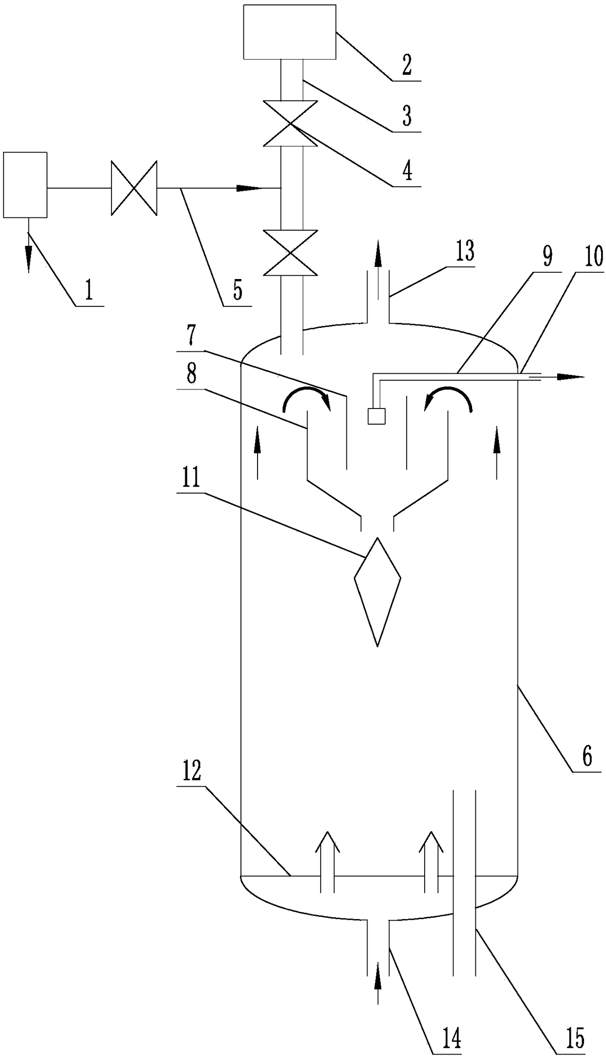
[0040] Such as figure 1 As shown, the ebullated bed hydrogenation reaction equipment of the present invention includes an ebullated bed hydrogenation reactor, a catalyst adding system and a dosing pipeline 1, wherein the catalyst adding system includes a catalyst storage tank 2 and a catalyst storage tank 2 connected with The catalyst delivery pipeline 3 in the internal space of the ebullating bed hydrogenation reactor, at least two valves 4 are arranged on the catalyst delivery pipeline 3, and the catalyst delivery pipeline 3 between the two valves 4 and the dosing pipeline 1 adopt anti- The hydrogen sulfide leakage pipeline 5 is connected, and at least one valve 4 is arranged on the hydrogen sulfide leakage prevention pipeline 5 . The dosing pipeline 1 is the outlet pipeline of the new hydrogen compressor or the outlet pipeline of the raw oil pump. The ebull...


PUM

PropertyMeasurementUnit
diameteraaaaaaaaaa
heightaaaaaaaaaa
diameteraaaaaaaaaa

Abstract

The invention belongs to the technical field of hydrogenation, and particularly relates to fluidized bed hydrogenation reaction equipment and a fluidized bed hydrogenation method. The fluidized bed hydrogenation reaction equipment comprises a fluidized bed hydrogenation reactor, a catalyst adding system and a catalyst adding pipeline, wherein the catalyst adding system comprises a catalyst storagetank and a catalyst delivering pipeline; the catalyst delivering pipeline communicates with the catalyst storage tank and inner space of the fluidized bed hydrogenation reactor; at least two valves are arranged on the catalyst delivering pipeline; the catalyst delivering pipeline between the two valves communicates with the catalyst adding pipeline by a hydrogen sulfide leakage prevention pipeline; and at least one valve is arranged on the hydrogen sulfide leakage prevention pipeline. By the fluidized bed hydrogenation reaction equipment, potential safety hazards caused by internal leakage due to frequent operation under special working conditions when a catalyst is added in a system are solved; the utilization rate of the reactor is further increased, the hydrogenation reaction effect isimproved, and the stability of operation of the device is improved; and the fluidized bed hydrogenation method is scientific and reasonable, and simple and practicable.

Description

technical field [0001] The invention belongs to the technical field of hydrogenation, and in particular relates to a fluidized bed hydrogenation reaction equipment and a fluidized bed hydrogenation method. Background technique [0002] Ebullated bed hydrogenation reaction refers to the process of hydrogenation reaction of feedstock oil (mainly in liquid phase) and hydrogen (gas phase) on catalyst (solid phase). Hydrogenation reaction mainly occurs in hydrodesulfurization, hydrodenitrogenation and hydrodeoxygenation , hydrogenation saturation, hydrocracking, etc. The reactor operates in the boiling state of gas, liquid and solid. The catalyst is in a boiling state driven by the raw material oil and hydrogen entering from the bottom of the reactor, which is in a completely different fluid state from the fixed bed reactor. The ebullating bed hydrogenation reaction can process low-quality feed oil with high metal and high asphaltene content. The reaction has the characteristics...

Claims


Application Information

Patent Timeline
Patent Type & Authority Applications(China)
IPC IPC(8): C10G45/06C10G45/08C10G45/14B01J8/24
CPCB01J8/24C10G45/06C10G45/08C10G45/14C10G2300/70
Inventor 王小英
Owner 上海竣铭化工工程设计有限公司
Why Eureka
Try Eureka