
Initial Alignment Method for Distributed Navigation System of Recoverable Space Vehicle

An initial alignment and navigation system technology, applied to instruments, measuring devices, etc., can solve the problems of complex systems, dependence on alignment methods, and high prices

Active Publication Date: 2020-12-11
BEIJING LANDSPACETECH CO LTD
View PDF5 Cites 0 Cited by
  • Summary
  • Abstract
  • Description
  • Claims
  • Application Information

AI Technical Summary

Problems solved by technology

[0005] Traditional rockets generally use optical transmission schemes for azimuth aiming. Although optical aiming can obtain high initial azimuth aiming accuracy, the guarantee conditions are complex and require the cooperation of the ground optical aiming system. Adding an azimuth aiming prism is a complex system with high investment costs. In addition, it is necessary to eliminate the influence of environmental factors such as external wind disturbance and strong light.
[0006] Although some space vehicles no longer need complex optical aiming systems, the initial azimuth alignment can be achieved by using the output information of the inertial measurement combination itself, but this alignment method depends on the high-precision inertial measurement combination, which is suitable for the traditional one-time Due to the high price of high-precision inertial units, in order to control the launch cost in recyclable space vehicles, in addition to the use of high-precision products for the inertial units in the instrument cabin, the first-stage and booster navigation subsystems generally use Low-to-medium-precision inertial group products, when the low-to-medium-precision inertial group performs autonomous azimuth alignment, the initial azimuth that meets the accuracy requirements cannot be obtained
Therefore, this alignment method is not fully applicable to the retrievable space vehicle of the distributed navigation system with inertial navigation units installed on different sub-levels

Method used


Image

  • Initial Alignment Method for Distributed Navigation System of Recoverable Space Vehicle
  • Initial Alignment Method for Distributed Navigation System of Recoverable Space Vehicle
  • Initial Alignment Method for Distributed Navigation System of Recoverable Space Vehicle

Examples


Embodiment Construction

[0054] In order to make the purposes, technical solutions and advantages of the embodiments of the present application clearer, the following will clearly illustrate the spirit of the content disclosed in the application with the accompanying drawings and detailed descriptions. After any person skilled in the art understands the embodiments of the content of the application , when it can be changed and modified by the technology taught in the content of the application, it does not depart from the spirit and scope of the content of the application.

[0055] The exemplary embodiments and descriptions of the present application are used to explain the present application, but not to limit the present application. In addition, elements / members with the same or similar numbers used in the drawings and embodiments are used to represent the same or similar parts.

[0056] The terms "first", "second", ... etc. used herein do not specifically refer to a sequence or order, nor are they...


PUM


Abstract

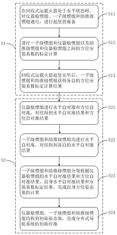
The application provides an initial alignment method for a distributed navigation system of a recoverable space vehicle, which includes: during the erection process of the rocket, performing a sub-level inertial group and an instrument cabin inertial group and a booster-level inertial group and instruments The calibration calculation of the azimuth installation coefficient between the cabin inertial groups; the instrument cabin inertial group performs horizontal self-alignment and azimuth self-alignment, and the horizontal self-alignment results and azimuth self-alignment results are obtained correspondingly; the first sub-level inertial group and booster The first-level inertial groups are all horizontally self-aligned, and their respective horizontal self-alignment results are obtained correspondingly; The self-horizontal self-alignment results and installation coefficient calibration results complete the calculation of its own azimuth and attitude angles; the initial attitude angles of the instrument cabin inertial group, the first-level inertial group and the booster-level inertial group are all obtained, and the initial alignment of the distributed navigation system is completed. allow. All levels of sub-navigation systems in this application can independently obtain high-precision azimuth alignment results.

Description

technical field [0001] The application belongs to the technical field of initial alignment of navigation systems, and in particular relates to an initial alignment method of a distributed navigation system of a recoverable space vehicle. Background technique [0002] With the continuous development of aerospace technology, how to reduce the cost of space launch has become one of the main challenges faced by the entire space industry, and the recyclability and reuse of space vehicles is an important measure to reduce launch costs. [0003] The overall configuration of the recoverable rocket is not significantly different from that of traditional space vehicles. However, due to the completion of the recovery of the first sub-stage and bundled boosters, compared with traditional space vehicles, except for the above In addition to installing navigation equipment in the instrument cabin of the first stage for the guidance and control of the ascent phase of the space vehicle, it i...

Claims


Application Information

Patent Timeline
Patent Type & Authority Patents(China)
IPC IPC(8): G01C25/00
CPCG01C25/005G01C25/00
Inventor 钟友武赵向楠徐孟晋
Owner BEIJING LANDSPACETECH CO LTD
Learn More