Vehicle parking control method and electronic equipment
A control method and vehicle technology, applied in the traffic control system, traffic control system, electrical components, etc. of road vehicles, can solve the problems of being unable to control the parking direction of shared vehicles, affecting the smooth removal of users, and affecting the appearance of the city
- Summary
- Abstract
- Description
- Claims
- Application Information
AI Technical Summary
Problems solved by technology
Method used
Image
Examples
Embodiment 1
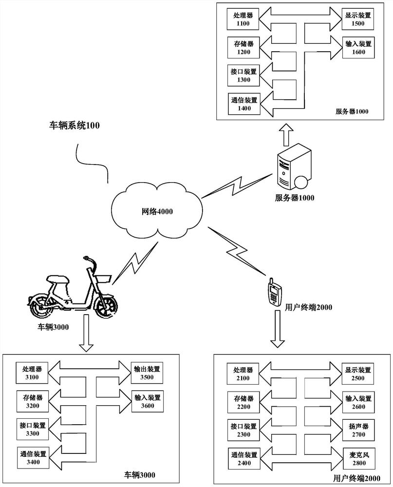
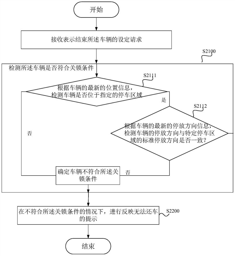
[0115] figure 2 is a schematic flowchart of a parking control method for a vehicle according to an embodiment. The method in this embodiment is implemented by the server. Below to figure 1 The server 1000, the vehicle 3000 and the user terminal 2000 of the user A are taken as examples to describe the parking control method of this embodiment.
[0116] according to figure 2 As shown, the parking control method of this embodiment may include the following steps S2100-S2200:
[0117] In step S2100, the server 1000 detects whether the vehicle 3000 meets the locking condition when receiving the indication that the use of the vehicle 3000 is over.
[0118] In this embodiment, the setting request is a lock request. The lock request may be sent from the user terminal 2000 to the server 1000, or may be sent from the vehicle 3000 to the server 1000, which is not limited here.
[0119] The lock request carries the user ID of user A and the vehicle ID of the vehicle 3000. In this ...
Embodiment 2
[0246] image 3 is a schematic flowchart of a parking control method for a vehicle according to an embodiment. The method in this embodiment is implemented by the vehicle. Below to figure 1 The server 1000, the vehicle 3000 and the user terminal 2000 of the user A are taken as examples to describe the parking control method of this embodiment.
[0247] according to figure 2 As shown, the parking control method of this embodiment may also include the following steps S2100-S2200:
[0248] In step S2100, when a setting request indicating that the vehicle 3000 is terminated is received, it is detected whether the vehicle 3000 meets the locking condition.
[0249] In this embodiment, the setting request is a return request triggered by the user through the return button provided by the vehicle 3000 .
[0250] Step S2200, when the detection result is that the vehicle 3000 does not meet the locking condition, a prompt is given reflecting that the vehicle cannot be returned.
...
Embodiment 3
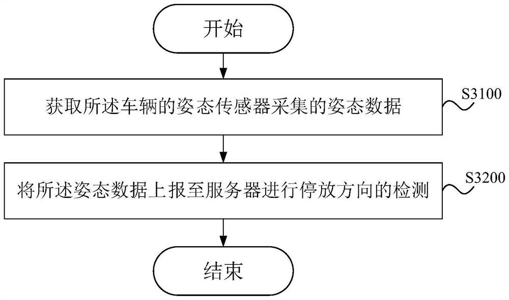
[0261] image 3 is a schematic flowchart of a parking control method for a vehicle according to an embodiment. The method of this embodiment is implemented by the vehicle, as follows figure 1 The server 1000, the vehicle 3000 and the user terminal 2000 of the user A are taken as examples to describe the parking control method of this embodiment.
[0262] Such as image 3 As shown, the parking control method of this embodiment may include the following steps S3100-S3200:
[0263] Step S3100, acquiring the attitude data collected by the attitude sensor of the vehicle 3000.
[0264] The attitude sensor includes at least an acceleration sensor and a geomagnetic sensor, and the attitude data includes acceleration data collected by the acceleration sensor and azimuth data collected by the geomagnetic sensor.
[0265] Step S3200, reporting the posture data to the server 1000 for detection of the parking direction.
[0266] In this embodiment, the detection of the parking direction...
PUM
 Abstract
Description
Claims
Application Information
 - R&D
- Intellectual Property
- Life Sciences
- Materials
- Tech Scout
- Unparalleled Data Quality
- Higher Quality Content
- 60% Fewer Hallucinations
Browse by: Latest US Patents, China's latest patents, Technical Efficacy Thesaurus, Application Domain, Technology Topic, Popular Technical Reports.
© 2025 PatSnap. All rights reserved.Legal|Privacy policy|Modern Slavery Act Transparency Statement|Sitemap|About US| Contact US: help@patsnap.com


