Toothpaste squeezer
A technology for squeezing toothpaste and toothpaste, which is applied in the field of toothpaste squeezers, and can solve the problems of wasting toothpaste, unable to control the amount of toothpaste squeezed out, and poor cleaning effect
- Summary
- Abstract
- Description
- Claims
- Application Information
AI Technical Summary
Problems solved by technology
Method used
Image
Examples
Embodiment 1
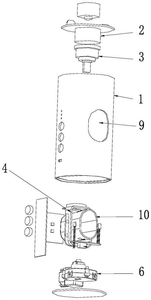
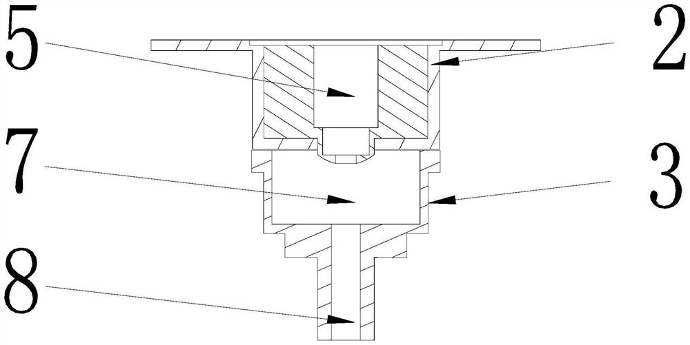
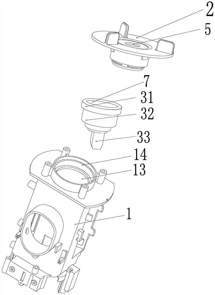
[0027] like figure 1 , figure 2 , image 3 , Image 6 and Figure 7 As shown, the present embodiment includes a housing 1, a fixed seat 2, a toothpaste extruding absorber 3, an extruding ring 4 and a driving device 6, the top of the housing 1 has a groove 13, and the bottom wall of the groove 13 is opened. There is an inlet 14, and the toothpaste squeezer 3 includes an upper section 31, a middle section 32 and a lower section 33, the bottom wall of the upper section is in contact with the bottom wall of the groove 13, and the middle section 32 and the lower section 33 pass through the inlet 14, so The bottom end of the fixed seat 2 enters the groove 13, the bottom wall of the fixed seat 2 contacts the top wall of the upper section 31, and the side wall of the fixed seat 2 is threadedly connected with the side wall of the groove 13;
[0028] The driving device 6 is fixed on the inner bottom wall of the shell 1, and the extruding ring 4 is slidably arranged in the shell 1. ...
Embodiment 2
[0046] like Figure 4 As shown, this embodiment is further limited on the basis of Embodiment 1. In this embodiment, the driving device 6 includes a first motor 51, a first housing 52, a first turbine 53, a first push rod 54, a first A rotating shaft 55 and a first worm 56; the first rotating shaft 55 is rotatably disposed on the inner bottom wall of the first casing 52, the first turbine 53 is fixed on the first rotating shaft 55, and the first motor 51 is fixed on On the first housing 52, the first worm 56 is connected to the output shaft of the first motor 51, the first worm 56 is engaged with the first worm wheel 53, and the first rotating shaft 55 has a first thread segment, and the first thread segment is located at the second Above a turbine 53, a first threaded hole is opened on the bottom end surface of the first push rod 54, the first threaded section is threadedly connected with the first threaded hole, and a through hole is opened on the top wall of the first shell...
Embodiment 3
[0049] like Figure 5 As shown, this embodiment is further limited on the basis of Embodiment 1. In this embodiment, the driving device 6 includes a second motor 61, a second housing 62, a second gear 63, a third gear 64, a fourth Gear 65, second shaft 66, fifth gear 67, sixth gear 68, third shaft 601, seventh gear 602, fourth shaft 603 and second push rod 604, the second motor 61 is fixed to the second housing 62, the second gear 63 is fixed on the output shaft of the second motor 61, and the second rotating shaft 66, the third rotating shaft 601 and the fourth rotating shaft 603 are all rotatably arranged on the inner wall of the second housing 62, and the The third gear 64 and the fourth gear 65 are fixed on the second rotating shaft 66, the fifth gear 67 and the sixth gear 68 are fixed on the third rotating shaft 601, and the seventh gear 602 is fixed on the fourth rotating shaft 603; The third gear 64 meshes with the second gear 63, the fourth gear 65 meshes with the fif...
PUM
 Abstract
Description
Claims
Application Information
 - R&D
- Intellectual Property
- Life Sciences
- Materials
- Tech Scout
- Unparalleled Data Quality
- Higher Quality Content
- 60% Fewer Hallucinations
Browse by: Latest US Patents, China's latest patents, Technical Efficacy Thesaurus, Application Domain, Technology Topic, Popular Technical Reports.
© 2025 PatSnap. All rights reserved.Legal|Privacy policy|Modern Slavery Act Transparency Statement|Sitemap|About US| Contact US: help@patsnap.com


