
An artificial seismic source device for exploration

A seismic source and artificial technology, applied in the direction of measuring devices, seismology, seismic energy generation, etc., can solve the problems of increasing equipment cost, high flatness requirements, and reducing test efficiency, so as to reduce the overall height, reduce the overall weight, improve The effect of applicability

Inactive Publication Date: 2021-01-12
田晓峰
View PDF6 Cites 0 Cited by
  • Summary
  • Abstract
  • Description
  • Claims
  • Application Information

AI Technical Summary

Problems solved by technology

Therefore, there are the following insufficient expenditures. First, because the vibration block generates kinetic energy under the action of gravity, the overall equipment needs to reach a certain height to make the kinetic energy of the vibration block large enough. If the overall height of the equipment is too high, it will not only increase the equipment The cost will also increase the finishing weight of the equipment, which is not conducive to field transportation; second, it is not convenient to control the kinetic energy of the vibration block, so it is not convenient to conduct experiments in areas of different nature
Third, there is no adjustment mechanism in the above-mentioned patent, so when in use, the flatness of the experimental site is required to be high, which will increase the labor workload of the experimenters and reduce the efficiency of the experiment

Method used


Image

  • An artificial seismic source device for exploration
  • An artificial seismic source device for exploration
  • An artificial seismic source device for exploration

Examples


Embodiment Construction

[0032] In order to make the object, technical solution and advantages of the present invention clearer, the present invention will be further described in detail below in conjunction with the accompanying drawings and embodiments. It should be understood that the specific embodiments described here are only used to explain the present invention, not to limit the present invention.

[0033] In describing the present invention, it should be understood that the terms "longitudinal", "transverse", "upper", "lower", "front", "rear", "left", "right", "vertical", The orientations or positional relationships indicated by "horizontal", "top", "bottom", "inner", "outer", etc. are based on the orientations or positional relationships shown in the drawings, and are only for the convenience of describing the present invention, rather than indicating or It should not be construed as limiting the invention by implying that a referenced device or element must have a particular orientation, be...


PUM


Abstract

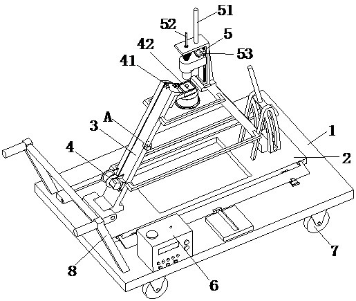
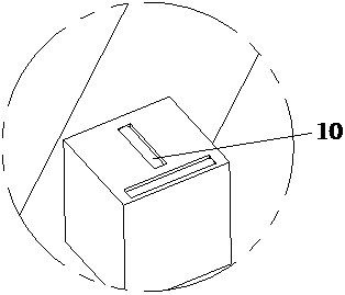
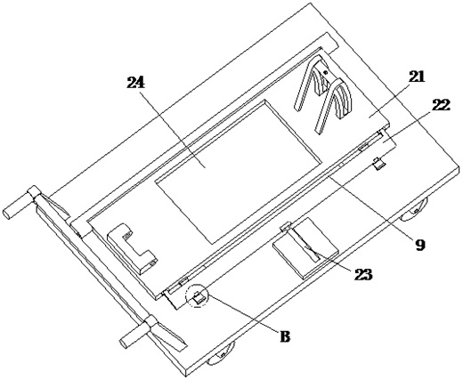
The invention relates to the field of seismic source devices, in particular to an artificial seismic source device for exploration. The seismic source device comprises a base, a first adjusting mechanism, a second adjusting mechanism, a lifting mechanism and a jacking mechanism; the lifting mechanism comprises a lifting assembly and a fixing assembly. The jacking mechanism comprises a jacking assembly, an impact assembly and a clamping assembly. The jacking assembly is arranged at the upper end of the lifting assembly, the impact assembly and the clamping assembly are both installed at the upper end of the jacking assembly; a power distribution cabinet is arranged on the base, four moving wheels are arranged at the lower end of the base, a pushing handle is arranged at one end of the base,a first through opening is formed in the middle of the base, and two gradienters perpendicular to each other are arranged on the second adjusting mechanism. Through adjustment of the first adjustingmechanism and the second adjusting mechanism, the requirement for the flatness of an experimental area can be lowered, the applicability of the device can be improved, through cooperative work of theimpact assembly and the fixing assembly, the kinetic energy of the balancing weight can be controlled and improved, and the applicability of the device is further improved.

Description

technical field [0001] The invention relates to the field of seismic source devices, in particular to an artificial seismic source device for exploration. Background technique [0002] Shallow seismic prospecting technology is one of the fracture survey methods used in shallow surface prospecting in the field. It mainly uses the characteristics of seismic wave propagation in different rocks and soils to detect shallow (usually tens to hundreds of meters) geological structures, determine Engineering geological and geophysical exploration of physical and mechanical parameters of rock and soil. [0003] Chinese patent No. CN201910143246.7 discloses an artificial seismic source device for geophysical exploration, including two No. 1 columns, a middle column and a No. 2 column. The top is provided with a drive box, and the inner wall of the drive box is provided with a telescopic movement mechanism. The outer wall of the center column is provided with a number of fixed holes eve...

Claims


Application Information

Patent Timeline
IPC IPC(8): G01V1/143G01V1/147G01V1/04
CPCG01V1/04G01V1/143G01V1/147
Inventor 田晓峰李稳臧怡然马策军徐勇熊伟邓晓果宋向辉郑成龙刘宇贤黄迅邱勇张彩军
Owner 田晓峰
Learn More