Pedestrian protection apparatus, and method of tuning load characteristic of the apparatus

a technology for protection apparatus and load characteristic, which is applied in the direction of roofs, bumpers, pedestrian/occupant safety arrangements, etc., can solve the problems of high component cost, troublesome mounting of the apparatus, and the disadvantages of both leg sweep members disclosed in the above publications, so as to facilitate the tuning of load characteristic, effectively suppressing an excessive increase of impact load, and the effect of improving the accuracy of load characteristi

Active Publication Date: 2009-10-06
KOJIMA PRESS IND CO LTD
View PDF24 Cites 37 Cited by
  • Summary
  • Abstract
  • Description
  • Claims
  • Application Information

AI Technical Summary

Benefits of technology

[0049](8) The method according to the above feature (6) or (7), wherein the center section of the plate includes a plurality of areas having mutually different rigidities, and the areas extend over a full dimension of the vehicle in a transverse direction, adjoin in the longitudinal direction of the vehicle, and are arranged in decreasing order of the rigidities from a front side of the center section. According to this feature, when a shock is inputted by a collision between the leg of the pedestrian and the front of the vehicle, the plate can also be bent at a boundary portion between the areas having mutually different rigidities in the center section, depending on the volume of the shock. This can effectively suppress an excessive increase of the impact load in the early stage of the shock input. Moreover, the load characteristic can be tuned more accurately.

Problems solved by technology

However, both the leg sweep members disclosed in the above publications have disadvantages to be overcome.
For this reason, the component cost is high, and it is troublesome to mount the apparatus.
In contrast, in the latter pedestrian protection apparatus formed of a metal pipe, the weight thereof is inevitably high, and it is difficult to form the apparatus in a shape that conforms to the shape of the front of the vehicle.
However, as the result of various tests and investigations, the present inventors found that the maximum value of the impact load inputted when the front section of the synthetic resin plate in the above pedestrian protection apparatus collided with the legs of a pedestrian did sometimes not reach a target value, that a reaction force required to sweep the legs away in the collision could not be ensured in this case, and that protection of the legs was insufficient.
However, in the known pedestrian protection apparatus having the above-described configuration, it is difficult to tune the load characteristic, so that it is difficult to optimize the same.
Furthermore, as for the load characteristic of the known apparatus, the pedestrian collision test also revealed that the amount of increase of the impact load per unit time in the early stage of the shock input was relatively small.

Method used


Image

  • Pedestrian protection apparatus, and method of tuning load characteristic of the apparatus
  • Pedestrian protection apparatus, and method of tuning load characteristic of the apparatus
  • Pedestrian protection apparatus, and method of tuning load characteristic of the apparatus

Examples


example 1

[0108]A leg sweep member serving as a first invention example having a configuration according to the present invention was formed and prepared by ejection molding using polypropylene. In this leg sweep member, the thickness and rigidity of a base plate become smaller in the order of a front section, a center section, and a rear section thereof, as shown in FIG. 10. The total dimension of the base plate in the depth direction is 200 mm, and the dimensions of the front section, the center section, and the rear section of the base plate are 50 mm, 100 mm, and 50 mm, respectively. The thicknesses of the front section, the center section, and the rear section are 3.0 mm, 2.5 mm, and 2.0 mm, respectively.

[0109]For comparison, a leg sweep member serving as a first comparative example was formed and prepared by ejection molding using polypropylene. In the first comparative example, the thicknesses of a front section, a center section, and a rear section of a base plate are 2.0 mm, 2.5 mm, ...

example 2

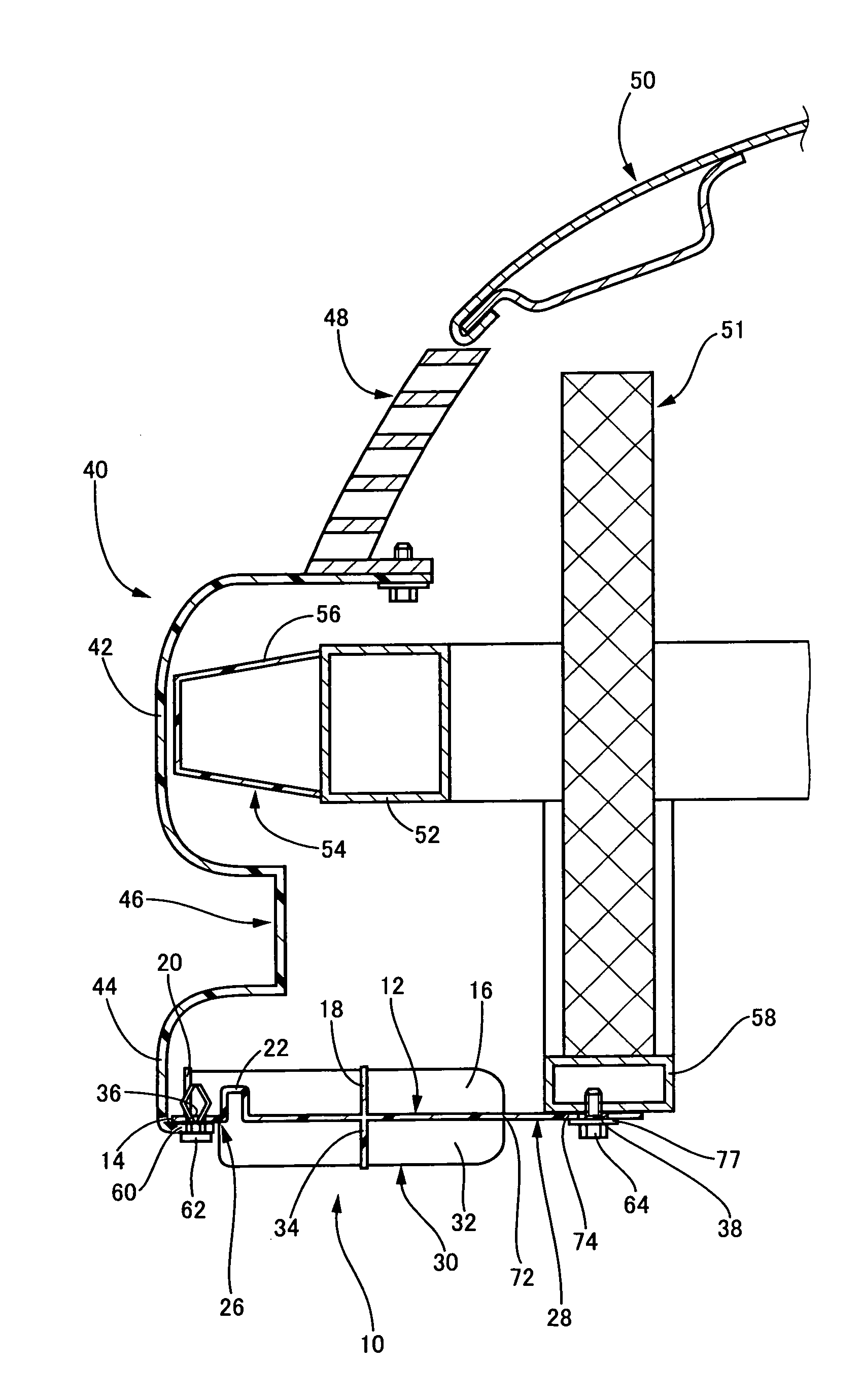
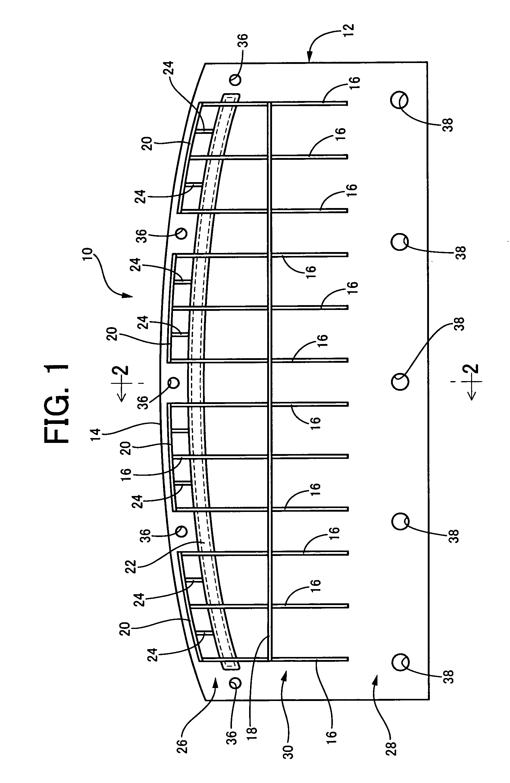
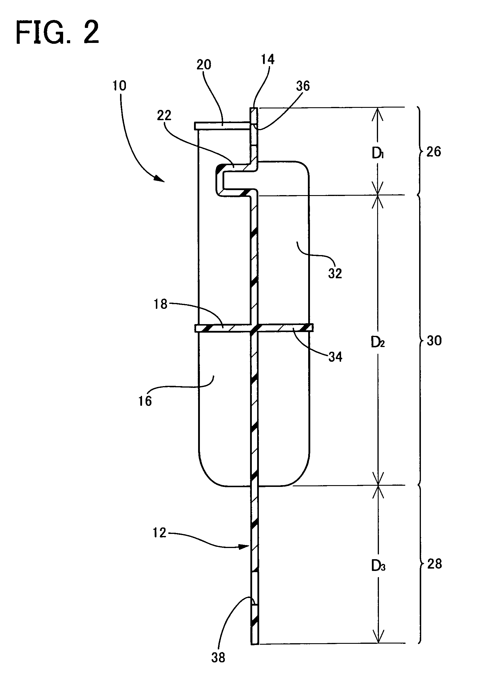
[0113]A leg sweep member having a configuration according to the present invention shown in FIGS. 1 to 3 was formed and prepared as a second invention example by ejection molding using polypropylene. In the second invention example, the rigidity of a base plate becomes lower in the order of a front section, a center section, and a rear section because of first to fifth ribs provided on the front section and the center section. The total dimension of the base plate in the depth direction is 190 mm, and the dimensions of the front section, the center section, and the rear section of the base are 30 mm, 110 mm, and 50 mm, respectively. The each of the first to fifth ribs provided on the front section and the center section is 3 mm in thickness, and are 25 mm in height.

[0114]In addition, a leg sweep member having a configuration according to the present invention was formed and prepared as a third invention example. The third invention example has the same basic structure as that of the...

example 3

[0117]First, the leg sweep member of the second invention example in the above-described second example was prepared. In addition, a fourth invention example having a configuration according to the present invention shown in FIG. 8, and having a basic structure similar to that of the second invention example was prepared. In the leg sweep member of the fourth invention example, an iron reinforcing plate having a predetermined flexural rigidity is fixed on a lower surface of a base plate so as to extend over a boundary portion and a front adjacent portion. The reinforcing plate has a thickness of 1.0 mm, and a dimension of 80 mm in the depth direction.

[0118]In a manner similar to that for the above-described first example, the two-types of leg sweep members of the second and fourth invention examples were installed at the fronts of actual vehicles (automobiles) to obtain two-types of test vehicles. Subsequently, a pedestrian collision test similar to that for the first example was co...


PUM


Abstract

In a pedestrian protection apparatus installed in a lower part of a front of a vehicle, a plate extends in a longitudinal direction of the vehicle, and includes a front section having at least a portion protruding from the front of the vehicle, a rear section fixed to the vehicle, and a center section provided between the front and rear sections. The front section is more rigid than the rear section, and the center section is less rigid than the front section and more rigid than the rear section.

Description

[0001]The present application is based on Japanese Patent Application No. 2005-304726 filed on Oct. 19, 2005, the contents of which are incorporated herein by reference.BACKGROUND OF THE INVENTION[0002]1. Field of the Invention[0003]The present invention relates to a pedestrian protection apparatus, and a method of tuning a load characteristic of the apparatus. More particularly, the present invention relates to an improved configuration of a pedestrian protection apparatus that is installed on a lower front side of a vehicle and that protects the legs of a pedestrian by sweeping the legs in contact with lower parts of the legs when the front of the vehicle collides with or comes into contact with the legs, and to a method of advantageously tuning a load characteristic of the apparatus.[0004]2. Description of the Related Art[0005]Various types of protection apparatuses are conventionally installed on front, rear, or side faces of vehicles, such as automobiles, mainly in order to abs...

Claims


Application Information

Patent Timeline
Patent Type & Authority Patents(United States)
IPC IPC(8): B60R19/18B60R19/12B60R19/16B60R19/54B60R21/34
CPCB60R21/34B60R2021/343
Inventor ITOU, KAORUOGURA, YOSHIHIROHASEGAWA, KUNIAKIFUKUKAWA, MASANOBUKUROKAWA, HIROKI
Owner KOJIMA PRESS IND CO LTD
Why Eureka
Try Eureka